fig 186A, Model
fig 186B, Model
fig 186C, Model
fig 185A, DECORMAQUETTE
fig 184A, Design
fig 184B, Design
fig 184C, Design
fig 184D, Design
fig 184E, Design
fig 184F, Design
fig 184G, Design
fig 184H, Design
fig 184I, Design
fig 183A, Structural Analysis
fig 183B, Structural Analysis
fig 183C, Structural Analysis
fig 183D, Structural Analysis
fig 183E, Structural Analysis
fig 183F, Structural Analysis
fig 183G, Structural Analysis
fig 183H, Structural Analysis
fig 183I, Structural Analysis
fig 183J, Structural Analysis
fig 183K, Structural Analysis
fig 182A, Masterplan final site gentbrugge
fig 182B, Masterplan final site gentbrugge, coworking
fig 182C, Masterplan final site gentbrugge
fig 182D, Masterplan final site gentbrugge
fig 182E, Masterplan final site gentbrugge
fig 182F, Masterplan final site gentbrugge
fig 181A, final drawings
fig 181B, final drawings
fig 180A, Site de Porre – primary structure model, A
fig 179A, Primary & New
fig 178A, Final model, B, 1:50
fig 177A, Final model
fig 177B, Final model, C
fig 176A, FINAL MODEL
fig 176B, FINAL MODEL
fig 175A, Project BOMA
fig 175B, Project BOMA
fig 175C, Project BOMA
fig 175D, Project BOMA
fig 175E, Project BOMA
fig 175F, Project BOMA
fig 175G, Project BOMA
fig 175H, Project BOMA
fig 174A, current structure analyse
fig 173A, model analyse
fig 171A, Analysis structure De Porre, Cantilever in concrete
fig 172A, Research new structures in combination with existing
fig 172B, Research new structures in combination with existing
fig 172C, Research new structures in combination with existing, acoustic solutions - new vs. existing (2)
fig 172D, Research new structures in combination with existing
fig 172E, Research new structures in combination with existing
fig 172F, Research new structures in combination with existing, A
fig 172G, Research new structures in combination with existing, B
fig 172H, Research new structures in combination with existing, Fase 1
fig 172I, Research new structures in combination with existing, fase 3
fig 170A, REFERENCES
fig 170B, REFERENCES
fig 170C, REFERENCES
fig 170D, REFERENCES
fig 170E, REFERENCES
fig 170F, REFERENCES
fig 168A, Tempory billboard on tempory structure
fig 169A, research / site model
fig 169B, research / site model
fig 169C, research / site model
fig 166A, FACADE DETAIL, The final fragmented detail of one of the three variations.
fig 166B, FACADE DETAIL, The final fragmented detail of one of the three variations.
fig 166C, FACADE DETAIL
fig 166D, FACADE DETAIL, Handmade concrete
fig 166E, FACADE DETAIL, Facade detail. Now waiting to remove the formwork.
fig 167A, WORK – tussen
fig 167B, WORK – tussen
fig 164A, CREE LCT building system, Floor slab with the holes in it for the steel bar of the columns
fig 164B, CREE LCT building system, wall piece with the columns attached
fig 165A, analysing site Gents Bakkershuis
fig 163A, Proces
fig 163B, Proces, steel connection
fig 163C, Proces, View from the street
fig 163D, Proces, section build on the ground
fig 163E, Proces
fig 162A, REFERENCE – ALDO VAN EYCK SONSBEEK PAVILJOEN
fig 160A, PROCES – AFBREKEN VS OPBOUW
fig 160B, PROCES – AFBREKEN VS OPBOUW
fig 161A, Conceptual Drawings ‘Zonder-Naamstraat Site’
fig 161B, Conceptual Drawings ‘Zonder-Naamstraat Site’
fig 161C, Conceptual Drawings ‘Zonder-Naamstraat Site’
fig 161D, Conceptual Drawings ‘Zonder-Naamstraat Site’
fig 159A, Research Drawings about the existing structure in the ‘zonder-naamstraat site’
fig 159B, Research Drawings about the existing structure in the ‘zonder-naamstraat site’
fig 159C, Research Drawings about the existing structure in the ‘zonder-naamstraat site’
fig 159D, Research Drawings about the existing structure in the ‘zonder-naamstraat site’
fig 159E, Research Drawings about the existing structure in the ‘zonder-naamstraat site’
fig 159F, Research Drawings about the existing structure in the ‘zonder-naamstraat site’
fig 159G, Research Drawings about the existing structure in the ‘zonder-naamstraat site’
fig 159H, Research Drawings about the existing structure in the ‘zonder-naamstraat site’
fig 159I, Research Drawings about the existing structure in the ‘zonder-naamstraat site’
fig 159J, Research Drawings about the existing structure in the ‘zonder-naamstraat site’
fig 159K, Research Drawings about the existing structure in the ‘zonder-naamstraat site’
fig 159L, Research Drawings about the existing structure in the ‘zonder-naamstraat site’
fig 159M, Research Drawings about the existing structure in the ‘zonder-naamstraat site’
fig 159N, Research Drawings about the existing structure in the ‘zonder-naamstraat site’
fig 157A, model masterplan
fig 158A, Model of the Site, The final position of the new added buildings.
fig 158B, Model of the Site, Model without any of the existing structures.
fig 156A, research structure, A
fig 155A, ISO
fig 153A, DRAWINGS
fig 153B, DRAWINGS
fig 153C, DRAWINGS
fig 153D, DRAWINGS
fig 153E, DRAWINGS
fig 153F, DRAWINGS
fig 153G, DRAWINGS
fig 153H, DRAWINGS
fig 153I, DRAWINGS
fig 153J, DRAWINGS
fig 154A, HAMAM – 17.04
fig 154B, HAMAM – 17.04
fig 151A, Site ‘Huidevetterken’, L-profile column
fig 151B, Site ‘Huidevetterken’, Steel detail
fig 152A, Reference: ALEXANDER BRODSKY 95 DEGREES RESTAURANT
fig 152B, Reference: ALEXANDER BRODSKY 95 DEGREES RESTAURANT
fig 152C, Reference: ALEXANDER BRODSKY 95 DEGREES RESTAURANT
fig 150A, Composite steel columns
fig 148A, Inversion of the field
fig 149A, Sketches
fig 149B, Sketches
fig 146A, Visit Industrial Natural stone factory
fig 146B, Visit Industrial Natural stone factory
fig 147A, ‘HUIDEVETTERKEN’ werkmaquette
fig 147B, ‘HUIDEVETTERKEN’ werkmaquette, existing situation plan
fig 147C, ‘HUIDEVETTERKEN’ werkmaquette
fig 145A, STRUCTURAL DESIGN PRINCIPLES
fig 145B, STRUCTURAL DESIGN PRINCIPLES
fig 145C, STRUCTURAL DESIGN PRINCIPLES
fig 145D, STRUCTURAL DESIGN PRINCIPLES
fig 145E, STRUCTURAL DESIGN PRINCIPLES
fig 145F, STRUCTURAL DESIGN PRINCIPLES
fig 145G, STRUCTURAL DESIGN PRINCIPLES
fig 144A, structural options. Isolating a container outside
fig 144B, structural options. Isolating a container outside
fig 142A, Urban design
fig 142B, Urban design
fig 143A, structural color
fig 143B, structural color
fig 140A, model making in the sun
fig 140B, model making in the sun
fig 141A, Site visit Sint-Martens-Latem
fig 141B, Site visit Sint-Martens-Latem
fig 141C, Site visit Sint-Martens-Latem
fig 141D, Site visit Sint-Martens-Latem
fig 141E, Site visit Sint-Martens-Latem
fig 141F, Site visit Sint-Martens-Latem
fig 141G, Site visit Sint-Martens-Latem
fig 139A, DT
fig 139B, DT
fig 138A, Sint – Amandsberg site, Gent. Details
fig 136A, Sint – Amandsberg site, Gent. Detail Model, OLYMPUS DIGITAL CAMERA
fig 137A, photos models
fig 137B, photos models
fig 137C, photos models
fig 137D, photos models
fig 137E, photos models
fig 135A, Final model
fig 133A, Final urban model
fig 133B, Final urban model
fig 133C, Final urban model
fig 134A, Structure models
fig 132A, 4 Column House
fig 130A, Example sites photos
fig 130B, Example sites photos
fig 130C, Example sites photos
fig 131A, Blekerijstraat site photos
fig 131B, Blekerijstraat site photos
fig 131C, Blekerijstraat site photos
fig 131D, Blekerijstraat site photos
fig 128A, Final drawings
fig 128B, Final drawings
fig 128C, Final drawings
fig 128D, Final drawings
fig 128E, Final drawings
fig 129A, Pictures site Nieuwevaart
fig 129B, Pictures site Nieuwevaart
fig 127A, Final
fig 127B, Final
fig 127C, Final
fig 125A, Site visit
fig 126A, URBAN FARM
fig 126B, URBAN FARM
fig 124A, Construction clt
fig 122A, Structure site Nieuwevaart Gent
fig 122B, Structure site Nieuwevaart Gent
fig 123A, New structures
fig 120A, Reference structure steel
fig 120B, Reference structure steel
fig 120C, Reference structure steel
fig 121A, Pictures Model
fig 121B, Pictures Model
fig 119A, Test model of 3 05 2017
fig 118A, Test model of 26 04 2017
fig 118B, Test model of 26 04 2017
fig 118C, Test model of 26 04 2017
fig 117A, Test model of 19 04 2017
fig 117B, Test model of 19 04 2017
fig 117C, Test model of 19 04 2017
fig 116A, Program, Freeing the site of cars by putting them in a tower of the same height as his modernistic neighbor.
fig 116B, Program, Entering the city via the E17 viaduct
fig 116C, Program
fig 116D, Program
fig 116E, Program, Program
fig 115A, Site visit
fig 115B, Site visit
fig 115C, Site visit
fig 115D, Site visit
fig 115E, Site visit
fig 114A, Existing structure
fig 114B, Existing structure, Axo
fig 114C, Existing structure, Section
fig 114D, Existing structure
fig 114E, Existing structure
fig 114F, Existing structure
fig 113A, Site Ijzerweglaan, City fabric
fig 113B, Site Ijzerweglaan, Island cut off by the river Schelde and the E17 Viaduct
fig 113C, Site Ijzerweglaan
fig 113D, Site Ijzerweglaan, Different existing typologies
fig 113E, Site Ijzerweglaan
fig 113F, Site Ijzerweglaan
fig 113G, Site Ijzerweglaan, A fence between a small neigborhood park and the 13.000 m2 site
fig 113H, Site Ijzerweglaan
fig 113I, Site Ijzerweglaan
fig 113J, Site Ijzerweglaan
fig 112A, Hans Chr. Hansen, Amager Koblingsstation, Facade detail
fig 112B, Hans Chr. Hansen, Amager Koblingsstation
fig 112C, Hans Chr. Hansen, Amager Koblingsstation
fig 111A, ComFlor® 51+
fig 111B, ComFlor® 51+
fig 111C, ComFlor® 51+
fig 110A, Current structure analyse
fig 110B, Current structure analyse
fig 110C, Current structure analyse
fig 110D, Current structure analyse
fig 110E, Current structure analyse
fig 110F, Current structure analyse
fig 110G, Current structure analyse
fig 108A, Gent Voorhaven PortService Warehouses, Large Warehouse facades
fig 108B, Gent Voorhaven PortService Warehouses, small warehouse
fig 108C, Gent Voorhaven PortService Warehouses, Bombed structure inside
fig 108D, Gent Voorhaven PortService Warehouses, Bombed structure old warehouses
fig 109A, Japanese House, 1907, Wood construction by 'master carpenter' Nishida Isaburo
fig 105A, WASSERIJ DER VLAANDEREN
fig 105B, WASSERIJ DER VLAANDEREN
fig 105C, WASSERIJ DER VLAANDEREN
fig 105D, WASSERIJ DER VLAANDEREN
fig 105E, WASSERIJ DER VLAANDEREN
fig 105F, WASSERIJ DER VLAANDEREN
fig 105G, WASSERIJ DER VLAANDEREN
fig 105H, WASSERIJ DER VLAANDEREN
fig 105I, WASSERIJ DER VLAANDEREN
fig 105J, WASSERIJ DER VLAANDEREN
fig 105K, WASSERIJ DER VLAANDEREN
fig 105L, WASSERIJ DER VLAANDEREN
fig 105M, WASSERIJ DER VLAANDEREN
fig 105N, WASSERIJ DER VLAANDEREN
fig 105O, WASSERIJ DER VLAANDEREN
fig 105P, WASSERIJ DER VLAANDEREN
fig 105Q, WASSERIJ DER VLAANDEREN
fig 105R, WASSERIJ DER VLAANDEREN
fig 105S, WASSERIJ DER VLAANDEREN
fig 105T, WASSERIJ DER VLAANDEREN
fig 105U, WASSERIJ DER VLAANDEREN
fig 105V, WASSERIJ DER VLAANDEREN
fig 105W, WASSERIJ DER VLAANDEREN
fig 105X, WASSERIJ DER VLAANDEREN
fig 106A, SITE
fig 106B, SITE
fig 107A, details in color
fig 107B, details in color
fig 107C, details in color
fig 107D, details in color
fig 107E, details in color
fig 107F, details in color
fig 104A, supporting points in sports
fig 104B, supporting points in sports
fig 104C, supporting points in sports
fig 102A, club house
fig 103A, RECTOLIGHT
fig 101A, WASSERIJ DER VLAANDEREN – ISO LOODS
fig 101B, WASSERIJ DER VLAANDEREN – ISO LOODS
fig 101C, WASSERIJ DER VLAANDEREN – ISO LOODS
fig 101D, WASSERIJ DER VLAANDEREN – ISO LOODS
fig 101E, WASSERIJ DER VLAANDEREN – ISO LOODS
fig 98A, Quick steel
fig 99A, Basic Concrete Prefab Construction, construction site
fig 99B, Basic Concrete Prefab Construction, Connection in the center of a diagonal buttress
fig 99C, Basic Concrete Prefab Construction, Top connection of a diagonal buttress
fig 99D, Basic Concrete Prefab Construction, Floor connection of a diagonal buttress
fig 99E, Basic Concrete Prefab Construction, prefab column and beam
fig 99F, Basic Concrete Prefab Construction, Columns with corbels and visible hole from weld plate cast into column for the beam connection.
fig 99G, Basic Concrete Prefab Construction, enfilade of the prefab system
fig 99H, Basic Concrete Prefab Construction, crane
fig 99I, Basic Concrete Prefab Construction, beam reinforcement
fig 100A, Steel Prefab Structure, construction site
fig 100B, Steel Prefab Structure, steel components joint
fig 100C, Steel Prefab Structure, steel components ridge joint
fig 100D, Steel Prefab Structure, steel components joint
fig 100E, Steel Prefab Structure, steel components ridge joint
fig 100F, Steel Prefab Structure
fig 100G, Steel Prefab Structure, steel components corner joint (inside)
fig 100H, Steel Prefab Structure, steel components ridge joint (inside)
fig 95A, Tube and Coupler Scaffolds
fig 95B, Tube and Coupler Scaffolds
fig 95C, Tube and Coupler Scaffolds
fig 95D, Tube and Coupler Scaffolds
fig 95E, Tube and Coupler Scaffolds
fig 95F, Tube and Coupler Scaffolds
fig 96A, mazda site koopvaardijlaan, Drawing of the interior structure on the exterior wall. Also the remnants of a connected wooden building that burned down in the 1970's is still visible in the drawing.
fig 96B, mazda site koopvaardijlaan, cast concrete column
fig 96C, mazda site koopvaardijlaan, View towards aisle on the side of the tracks.
fig 96D, mazda site koopvaardijlaan
fig 96E, mazda site koopvaardijlaan
fig 96F, mazda site koopvaardijlaan
fig 96G, mazda site koopvaardijlaan
fig 96H, mazda site koopvaardijlaan
fig 97A, SITE & BUILDING ANALYSIS, Exploded view from different construction segments
fig 97B, SITE & BUILDING ANALYSIS, Detailed plan from below and above the ground
fig 93A, TECHNICAL DETAILS, Technical detail on the guiding rails
fig 93B, TECHNICAL DETAILS, Technical detail on the connection between the steel structure & foundation
fig 94A, INDUSTRIAL CONSTRUCTION SITE, Prefab structure
fig 94B, INDUSTRIAL CONSTRUCTION SITE, Two truss crossing
fig 94C, INDUSTRIAL CONSTRUCTION SITE, Cross bracing of the structure
fig 90A, Connection of a steel beam to a concrete wall
fig 90B, Connection of a steel beam to a concrete wall
fig 91A, MODEL #1, Interior wooden structure
fig 91B, MODEL #1, Interior wooden structure
fig 92A, MODEL #2, Cross-section model of the gasholder
fig 92B, MODEL #2, Cross-section model of the gasholder
fig 92C, MODEL #2, Cross-section model of the gasholder
fig 88A, MODEL #4
fig 89A, Study models
fig 89B, Study models
fig 89C, Study models, Using the same logic to connect two pieces to find the right length
fig 84A, Study models, Model 1/25
fig 84B, Study models, Model 1/25
fig 84C, Study models, Model 1/25
fig 85A, Analysis of the site, structure, detail, 2D build-up of steel truss
fig 85B, Analysis of the site, structure, detail, isometric
fig 85C, Analysis of the site, structure, detail, isometric
fig 85D, Analysis of the site, structure, detail, isometric
fig 85E, Analysis of the site, structure, detail, isometric
fig 85F, Analysis of the site, structure, detail, Site
fig 85G, Analysis of the site, structure, detail, isometric
fig 86A, Wittemolenstraat, Sint – Amandsberg, OLYMPUS DIGITAL CAMERA
fig 86B, Wittemolenstraat, Sint – Amandsberg, OLYMPUS DIGITAL CAMERA
fig 87A, Analysis structure De Porre, De Porre - floorplan
fig 87B, Analysis structure De Porre, De Porre - level +1
fig 87C, Analysis structure De Porre, Isometric view - surroundings
fig 87D, Analysis structure De Porre, Isometric view - structure
fig 81A, ANALYSE EXISTING STRUCTURES
fig 82A, Analysis structure “De Porre”, Part of structure with cantilever
fig 82B, Analysis structure “De Porre”, Part of structure with cantilever - top
fig 82C, Analysis structure “De Porre”, Part of structure with cantilever
fig 83A, SITE ANALYSE
fig 83B, SITE ANALYSE
fig 83C, SITE ANALYSE
fig 79A, detail construction garage box, construction detail precast concrete elements
fig 80A, Site analyse
fig 80B, Site analyse
fig 80C, Site analyse
fig 80D, Site analyse
fig 80E, Site analyse
fig 80F, Site analyse
fig 80G, Site analyse
fig 80H, Site analyse
fig 80I, Site analyse
fig 80J, Site analyse, top view
fig 80K, Site analyse
fig 80L, Site analyse
fig 80M, Site analyse
fig 80N, Site analyse
fig 80O, Site analyse
fig 80P, Site analyse
fig 80Q, Site analyse
fig 80R, Site analyse
fig 80S, Site analyse
fig 80T, Site analyse
fig 78A, Site Secondary structure, OLYMPUS DIGITAL CAMERA
fig 78B, Site Secondary structure, OLYMPUS DIGITAL CAMERA
fig 78C, Site Secondary structure, OLYMPUS DIGITAL CAMERA
fig 78D, Site Secondary structure, OLYMPUS DIGITAL CAMERA
fig 74A, MODEL – WASSERIJ DER VLAANDEREN, WASSERIJ DER VLAANDEREN
fig 75A, Construction details of a car dealers garage, Joint of a column, primary and secondary roof beams.
fig 75B, Construction details of a car dealers garage, Technical detail on the guiding rails
fig 75C, Construction details of a car dealers garage, Technical detail on the connection between the steel structure & foundation
fig 76A, Project Kievit
fig 76B, Project Kievit
fig 76C, Project Kievit
fig 76D, Project Kievit
fig 77A, Concrete building elements
fig 77B, Concrete building elements
fig 77C, Concrete building elements
fig 77D, Concrete building elements
fig 77E, Concrete building elements
fig 77F, Concrete building elements
fig 77G, Concrete building elements
fig 77H, Concrete building elements
fig 71A, axonometric view on docks site
fig 72A, Structure of the big warehouse on docks site
fig 73A, Construction details of the warehouse on site
fig 73B, Construction details of the warehouse on site
fig 73C, Construction details of the warehouse on site
fig 70A, Pictures Nonnemeersstraat, Ghent
fig 70B, Pictures Nonnemeersstraat, Ghent
fig 69A, models
fig 67A, College Football Hall of Fame, Robert Venturi & Denise Scott Brown
fig 67B, College Football Hall of Fame, Robert Venturi & Denise Scott Brown
fig 68A, collage: walls around the field
fig 63A, Model tests
fig 64A, DOME – EPS + SPRAYED CONCRETE, DOME - EPS + SPRAYED CONCRETE
fig 64B, DOME – EPS + SPRAYED CONCRETE
fig 64C, DOME – EPS + SPRAYED CONCRETE
fig 64D, DOME – EPS + SPRAYED CONCRETE
fig 64E, DOME – EPS + SPRAYED CONCRETE
fig 64F, DOME – EPS + SPRAYED CONCRETE
fig 64G, DOME – EPS + SPRAYED CONCRETE
fig 65A, test model: terraces &facade
fig 66A, Test Model – Drawing
fig 59A, PUNCHED/PUNCTURED BEAM
fig 59B, PUNCHED/PUNCTURED BEAM
fig 59C, PUNCHED/PUNCTURED BEAM
fig 60A, SIMPLE CONSTRUCTION
fig 60B, SIMPLE CONSTRUCTION
fig 60C, SIMPLE CONSTRUCTION
fig 61A, roof on/between containers
fig 61B, roof on/between containers
fig 61C, roof on/between containers
fig 61D, roof on/between containers
fig 61E, roof on/between containers, KONICA MINOLTA DIGITAL CAMERA
fig 61F, roof on/between containers
fig 62A, container cut outs
fig 62B, container cut outs
fig 62C, container cut outs
fig 62D, container cut outs
fig 54A, HOLZER KOBLER ARCHITEKTUREN FRANKIE & JOHNNY STUDENT HOUSING PLÄNTERWALD
fig 54B, HOLZER KOBLER ARCHITEKTUREN FRANKIE & JOHNNY STUDENT HOUSING PLÄNTERWALD
fig 54C, HOLZER KOBLER ARCHITEKTUREN FRANKIE & JOHNNY STUDENT HOUSING PLÄNTERWALD
fig 54D, HOLZER KOBLER ARCHITEKTUREN FRANKIE & JOHNNY STUDENT HOUSING PLÄNTERWALD
fig 54E, HOLZER KOBLER ARCHITEKTUREN FRANKIE & JOHNNY STUDENT HOUSING PLÄNTERWALD
fig 54F, HOLZER KOBLER ARCHITEKTUREN FRANKIE & JOHNNY STUDENT HOUSING PLÄNTERWALD
fig 55A, section draft
fig 56A, sketches container : Stacking;Connection
fig 56B, sketches container : Stacking;Connection
fig 56C, sketches container : Stacking;Connection
fig 56D, sketches container : Stacking;Connection
fig 56E, sketches container : Stacking;Connection
fig 57A, Mid-Process model
fig 58A, Model #1
fig 58B, Model #1
fig 49A, Model #2
fig 50A, OLD vs. NEW
fig 51A, Project Nonnemeersstraat, Ghent
fig 51B, Project Nonnemeersstraat, Ghent
fig 51C, Project Nonnemeersstraat, Ghent
fig 51D, Project Nonnemeersstraat, Ghent
fig 51E, Project Nonnemeersstraat, Ghent
fig 51F, Project Nonnemeersstraat, Ghent
fig 51G, Project Nonnemeersstraat, Ghent
fig 51H, Project Nonnemeersstraat, Ghent
fig 51I, Project Nonnemeersstraat, Ghent
fig 51J, Project Nonnemeersstraat, Ghent
fig 51K, Project Nonnemeersstraat, Ghent
fig 51L, Project Nonnemeersstraat, Ghent
fig 51M, Project Nonnemeersstraat, Ghent
fig 51N, Project Nonnemeersstraat, Ghent
fig 51O, Project Nonnemeersstraat, Ghent
fig 51P, Project Nonnemeersstraat, Ghent
fig 52A, CONSTRUCTION SITE
fig 53A, visit construction site
fig 53B, visit construction site
fig 53C, visit construction site
fig 47A, Every Big Box has its structure
fig 47B, Every Big Box has its structure
fig 48A, model vs Spa reine
fig 46A, masterplan site gentbrugge
fig 46B, masterplan site gentbrugge
fig 46C, masterplan site gentbrugge
fig 45A, shipping container
fig 45B, shipping container
fig 45C, shipping container
fig 41A, Steel structure
fig 41B, Steel structure
fig 41C, Steel structure
fig 41D, Steel structure
fig 42A, Renovation factory Kotrijk
fig 42B, Renovation factory Kotrijk
fig 42C, Renovation factory Kotrijk
fig 42D, Renovation factory Kotrijk
fig 43A, Hot Rivet, knooppunt staalstructuur
fig 44A, STEEL JOINT
fig 36A, Woonzorgcentrum Van Lierde, the blocks can be used for structural and non-structural purposes
fig 37A, corner of the sport fence
fig 38A, pergola without roof connection
fig 39A, Japan wood connection in chamonix
fig 40A, Schuur Gentbrugge – Site
fig 40B, Schuur Gentbrugge – Site
fig 40C, Schuur Gentbrugge – Site
fig 40D, Schuur Gentbrugge – Site
fig 40E, Schuur Gentbrugge – Site
fig 32A, Hangar INCO, Exploded construction of the hangar
fig 32B, Hangar INCO, Composition detail of brick, concrete columns and plinth
fig 32C, Hangar INCO
fig 32D, Hangar INCO
fig 32E, Hangar INCO, Skylight
fig 32F, Hangar INCO, Skylight
fig 32G, Hangar INCO, Concrete columns, laminated wooden beams
fig 32H, Hangar INCO, Concrete columns & beams
fig 33A, Factory “De Porre” – Gentbrugge, Factory Mill De Porre Gentbrugge - site
fig 33B, Factory “De Porre” – Gentbrugge, Factory Mill De Porre - Primary structure
fig 33C, Factory “De Porre” – Gentbrugge, Factory Mill De Porre Gentbrugge - Concrete ceiling
fig 33D, Factory “De Porre” – Gentbrugge, Factory Mill De Porre - fragment
fig 33E, Factory “De Porre” – Gentbrugge, Factory Mill De Porre - Concrete cantilever
fig 33F, Factory “De Porre” – Gentbrugge, Factory Mill De Porre Gentbrugge - steel truss
fig 34A, Lignatur floor/ roof element, Lignatur floor element - hollow core slab
fig 34B, Lignatur floor/ roof element, Lignatur floor element - Detail possibilties ducts
fig 35A, Floor systems of bricks
fig 35B, Floor systems of bricks
fig 35C, Floor systems of bricks
fig 35D, Floor systems of bricks
fig 24A, Steel truss, center piece
fig 24B, Steel truss, Beam and truss connection
fig 25A, Hole deck, Holedeck construction
fig 25B, Hole deck
fig 26A, Lumat Site Gent
fig 26B, Lumat Site Gent
fig 26C, Lumat Site Gent
fig 27A, Types of steel trusses
fig 28A, Industrial warehouse, connection between foundation and column
fig 28B, Industrial warehouse, connection between column and beam
fig 28C, Industrial warehouse
fig 28D, Industrial warehouse, connection between beams
fig 28E, Industrial warehouse, connection between column and beam
fig 28F, Industrial warehouse
fig 29A, STEKO – Building Blocks, The basic elements of the STEKO® building system
fig 29B, STEKO – Building Blocks
fig 29C, STEKO – Building Blocks
fig 30A, Silos, tanks & holders, Bottom-up construction
fig 30B, Silos, tanks & holders, Interior view
fig 30C, Silos, tanks & holders, Assembling the topcover
fig 30D, Silos, tanks & holders, Surreal image
fig 31A, Silos, tanks & holders, Fully assembled
fig 31B, Silos, tanks & holders, Positioning the different panels
fig 31C, Silos, tanks & holders, Pre-asssembly of the different panels
fig 15A, SILOS, TANKS & HOLDERS, Rotating the panels allows vertical forces to be guided down
fig 15B, SILOS, TANKS & HOLDERS, Basic dimensions of a cold rolled steel silo panel
fig 16A, SITE VISIT, The large wooden beams ready to be installed.
fig 16B, SITE VISIT, Prefabricated elements are fixed on the columns.
fig 16C, SITE VISIT, Steel elements where the secondary wooden beams will be fixed on.
fig 16D, SITE VISIT, The building of the extension of the store of Aveve.
fig 16E, SITE VISIT, The existing store of Aveve.
fig 17A, SITE VISIT °2, On top you can see the combination of the concrete columns with the steel trusses.
fig 17B, SITE VISIT °2, Prefabricated concrete elements fits perfectly in each other.
fig 17C, SITE VISIT °2, The holes in the beams are made to put ducts through them.
fig 17D, SITE VISIT °2, Prefabricated concrete elements fits perfectly in each other.
fig 17E, SITE VISIT °2, Prefabricated beams and columns with on top the prefabricated vaults.
fig 17F, SITE VISIT °2, The structure is filled up with brick between the columns.
fig 17G, SITE VISIT °2, The prefabricated vaults.
fig 17H, SITE VISIT °2, Against the primary structure, facade elements are fixed.
fig 18A, Wood Hollow Core Slab
fig 18B, Wood Hollow Core Slab
fig 21A, Tram depot Marconi – site visit
fig 21B, Tram depot Marconi – site visit
fig 21C, Tram depot Marconi – site visit
fig 22A, factory Gentbrugge – Site, wooden beam pattern
fig 22B, factory Gentbrugge – Site
fig 22C, factory Gentbrugge – Site
fig 22D, factory Gentbrugge – Site, masonry
fig 22E, factory Gentbrugge – Site, existing structure
fig 23A, Poco Loco – Fully automatic warehouse, View from the street
fig 23B, Poco Loco – Fully automatic warehouse, section build on the ground
fig 23C, Poco Loco – Fully automatic warehouse, connection of 2 different sections
fig 23D, Poco Loco – Fully automatic warehouse, reinforcement for windloads
fig 23E, Poco Loco – Fully automatic warehouse, connection
fig 23F, Poco Loco – Fully automatic warehouse, detail of a steel beam
fig 23G, Poco Loco – Fully automatic warehouse, reinforcement on the top for the windloads
fig 10A, CORRUGATED WEB BEAM, Production GLP Beam
fig 10B, CORRUGATED WEB BEAM, Connection GLP to GLP
fig 10C, CORRUGATED WEB BEAM, Connection GLP to column
fig 10D, CORRUGATED WEB BEAM, Example project
fig 10E, CORRUGATED WEB BEAM, Example project 2
fig 11A, FC Muide
fig 11B, FC Muide
fig 11C, FC Muide
fig 12A, Industrial Structure
fig 12B, Industrial Structure
fig 13A, Arrival_Tower
fig 14A, Industrial project
fig 14B, Industrial project
fig 14C, Industrial project
fig 14D, Industrial project
fig 14E, Industrial project
fig 14F, Industrial project
fig 14G, Industrial project
fig 14H, Industrial project
fig 14I, Industrial project
fig 14J, Industrial project
fig 14K, Industrial project
fig 14L, Industrial project
fig 14M, Industrial project
fig 14N, Industrial project
fig 14O, Industrial project
fig 14P, Industrial project
fig 14Q, Industrial project
fig 14R, Industrial project
fig 14S, Industrial project
fig 14T, Industrial project
fig 14U, Industrial project
fig 9A, Getting some help, Getting some help.
fig 8A, FRAC, Dunkerque by Lacaton & Vasal, Frontal Facade, showing the old building and new 'copy' next to each other
fig 8B, FRAC, Dunkerque by Lacaton & Vasal
fig 8C, FRAC, Dunkerque by Lacaton & Vasal, The beautiful transparency of the skin invites the outside world in and ceases to be distant as an art institution might be. The shell does only what it is meant to do, protect its core from the outer elements. The glass and steel myth was reinterpreted and altered with a plastic and steel frame.
fig 8D, FRAC, Dunkerque by Lacaton & Vasal, Steel connection between the old and new building.
fig 8E, FRAC, Dunkerque by Lacaton & Vasal, The climactic gain from this greenhouse concept is an ingenious solution for the demand of more self-sufficient buildings and energy efficiency. The circulation spaces function as a buffer between the spaces and the one-layered shell.
fig 8F, FRAC, Dunkerque by Lacaton & Vasal, Where the spaces themselves border the shell, at the upper level aswell as the vertical separation space between the 2 monoliths, another ingenious transparant envelope is applied. Convexly shaped hard plastic is placed in layers against eachother so an insulating layer of air is trapped inside this half orb space.
fig 8G, FRAC, Dunkerque by Lacaton & Vasal, Detailed section
fig 8H, FRAC, Dunkerque by Lacaton & Vasal, Front facade detail
fig 7A, types of compound beam
fig 6A, Drawing connection of steel structure
fig 6B, Drawing connection of steel structure
fig 5A, Concrete Structure, Concrete Grid Structure
fig 5B, Concrete Structure, Concrete Skylight
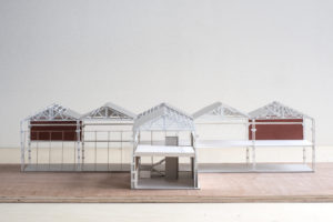
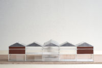
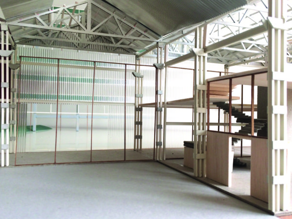
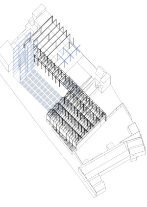
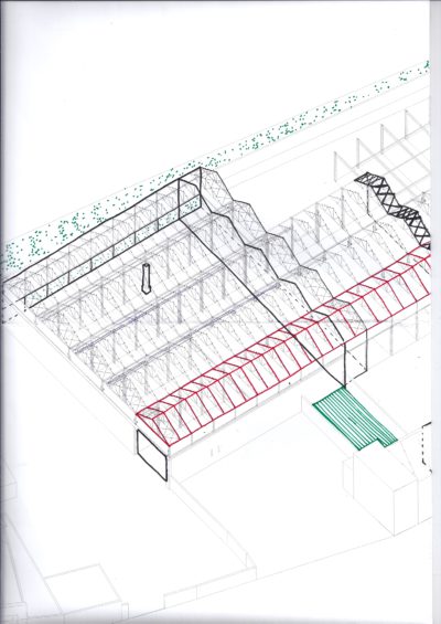
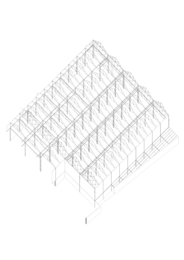
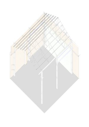
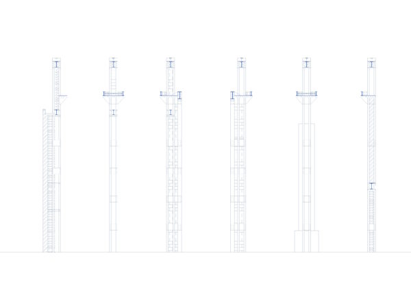
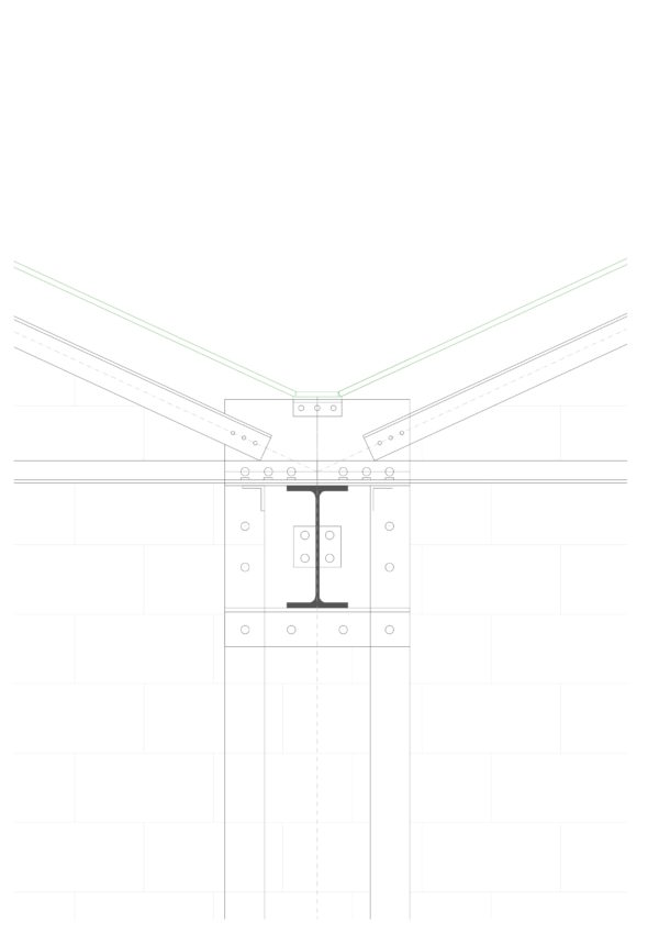
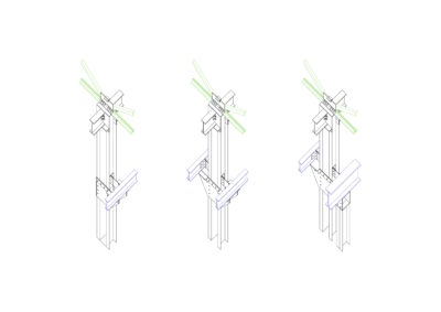
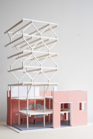
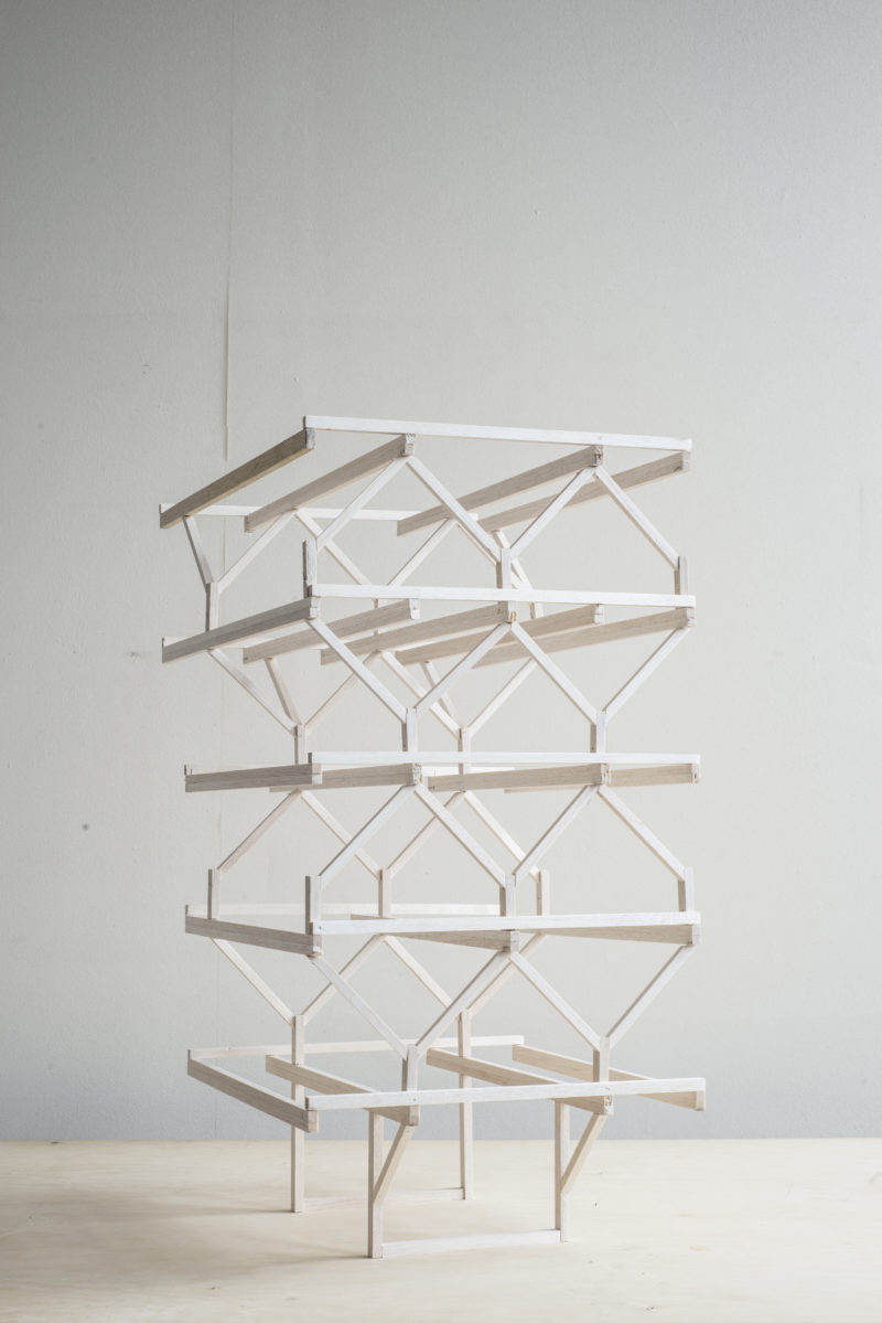
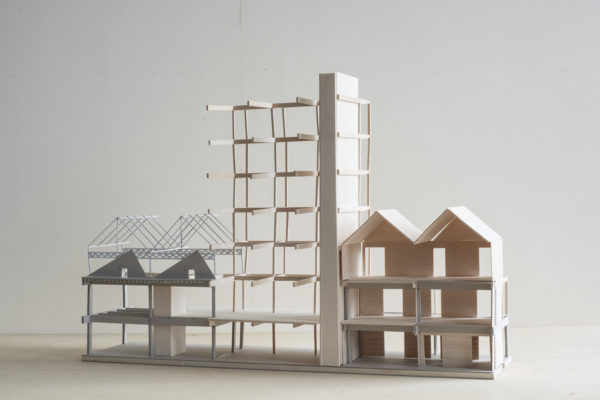
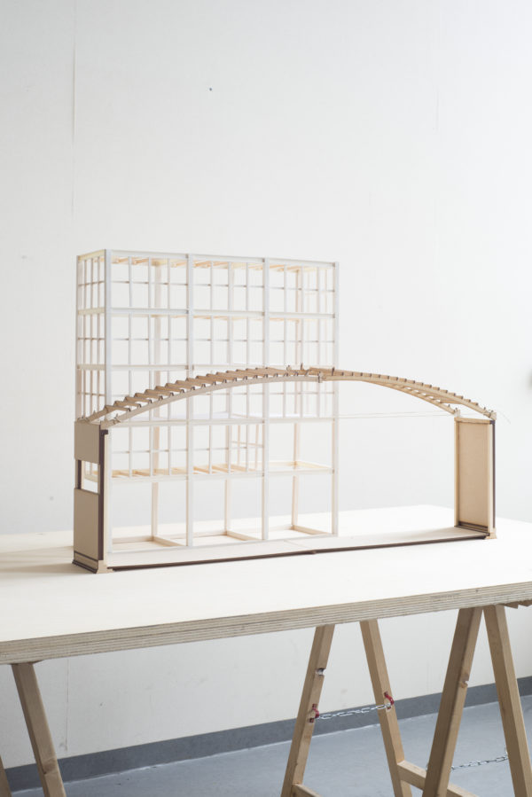
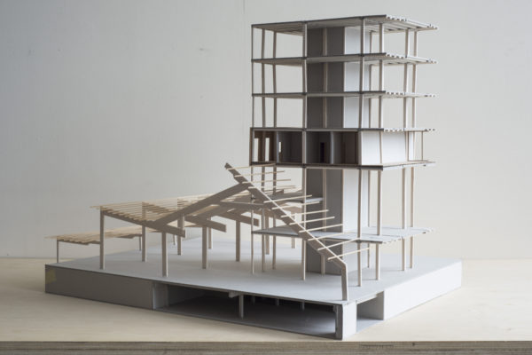
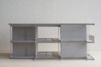
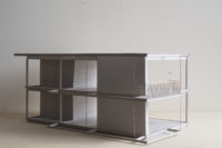
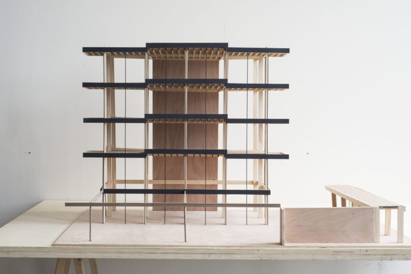
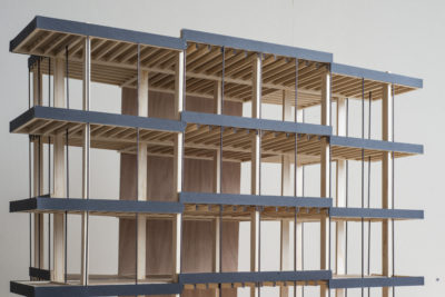
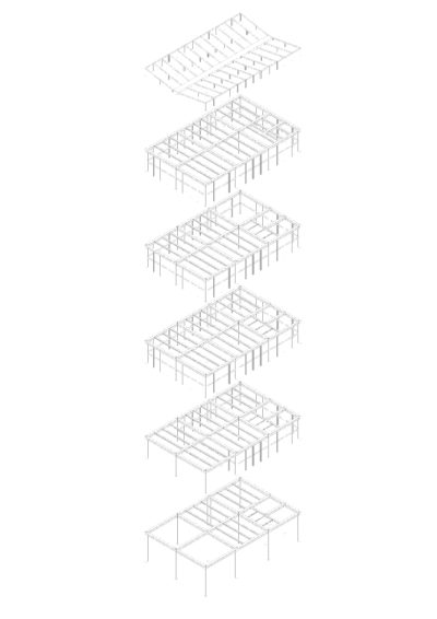
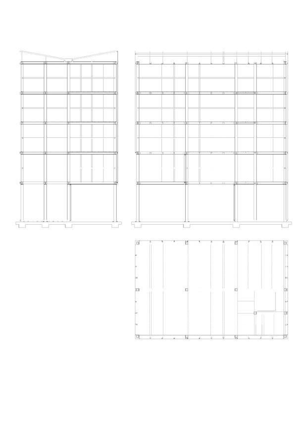
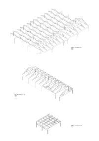
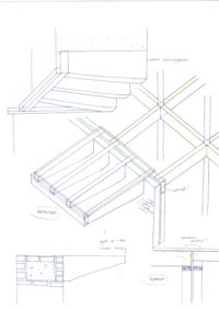
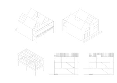
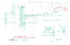
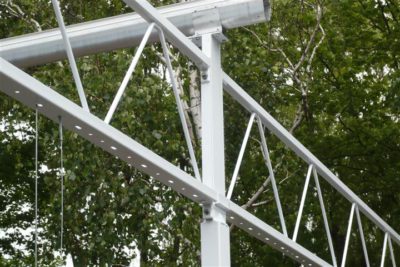
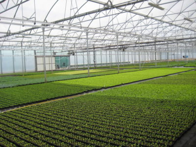
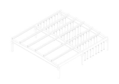
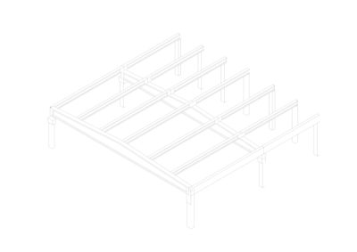
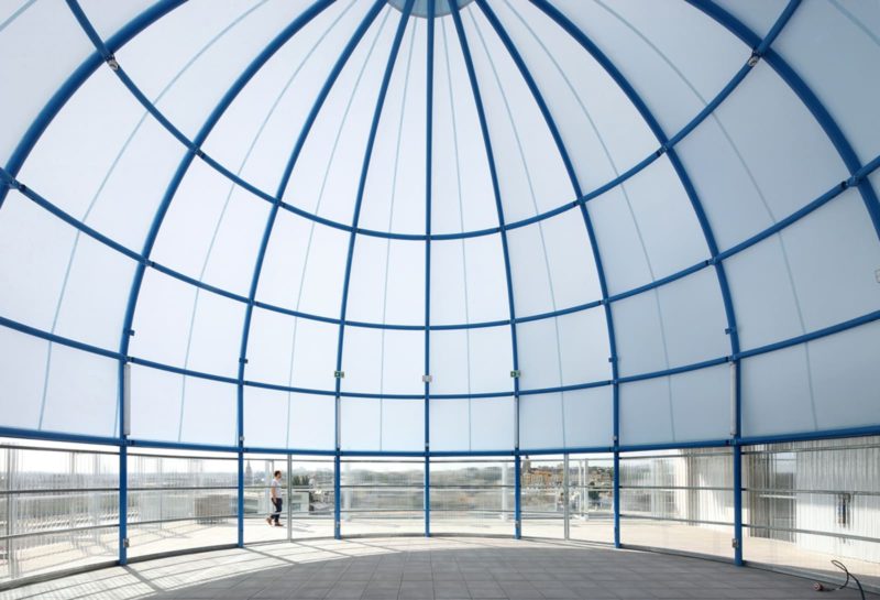
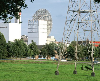
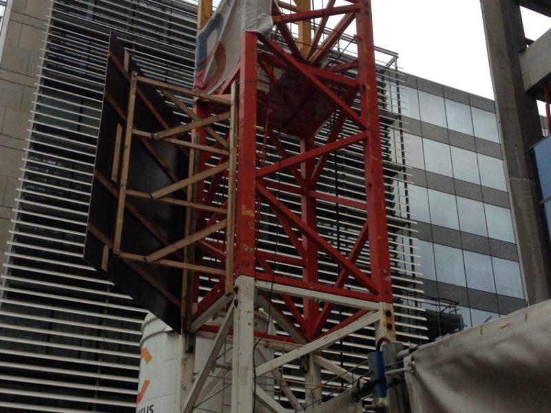
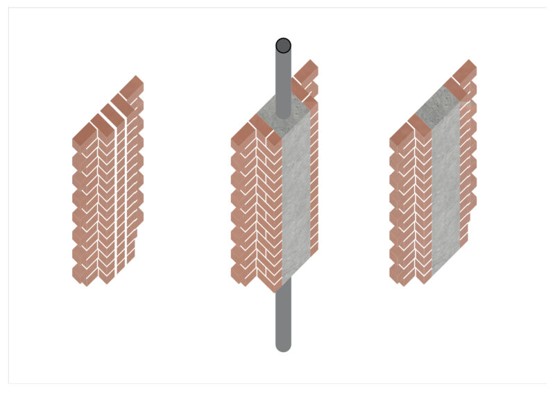
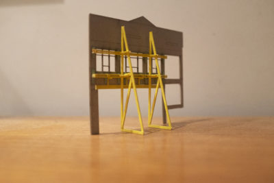
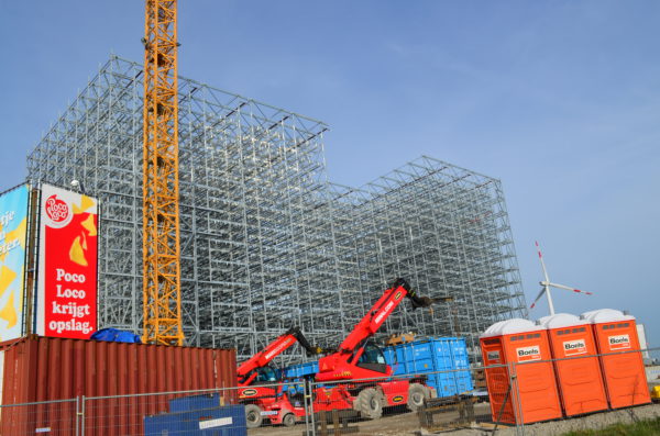
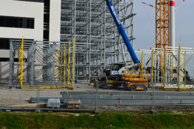
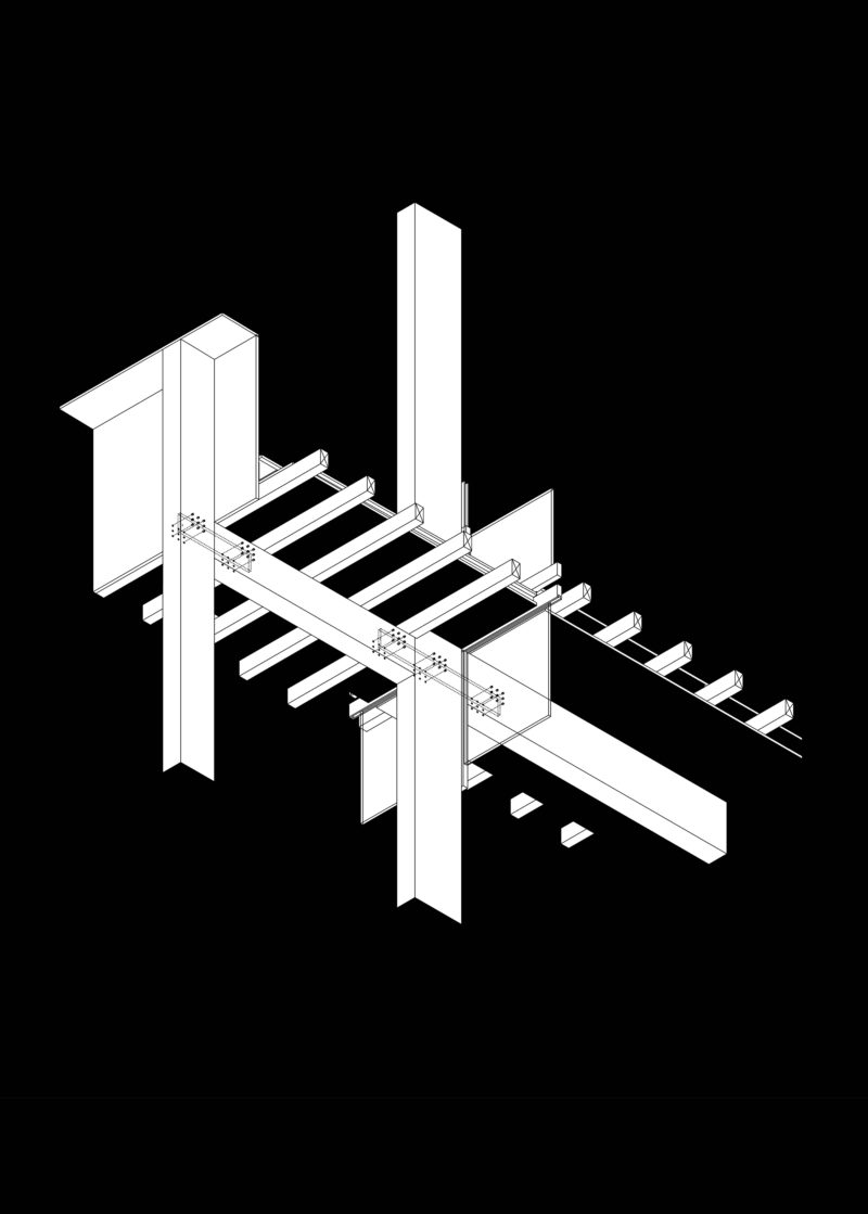
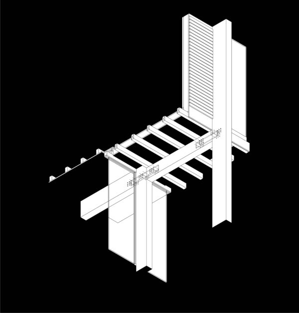
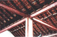
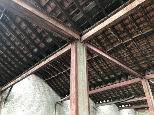
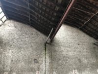
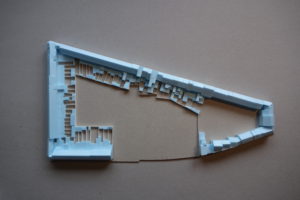
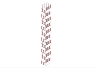
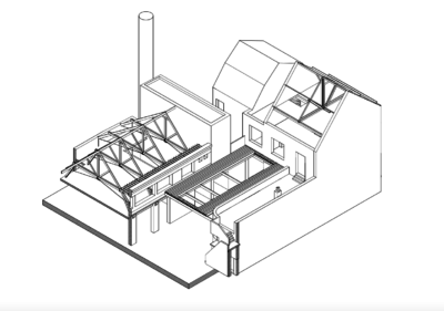
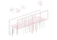
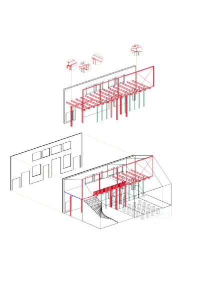
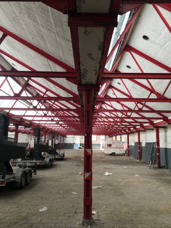
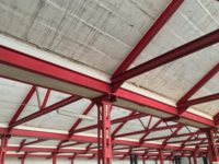
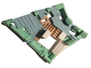
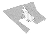
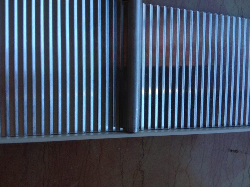
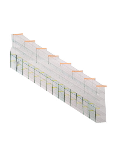
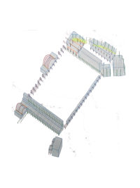
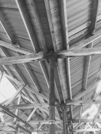
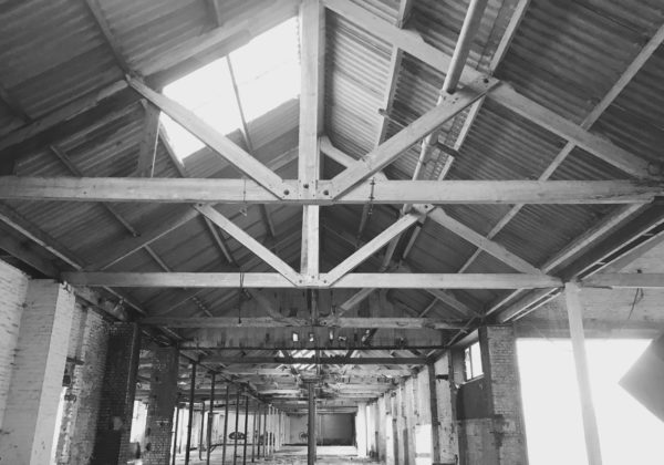
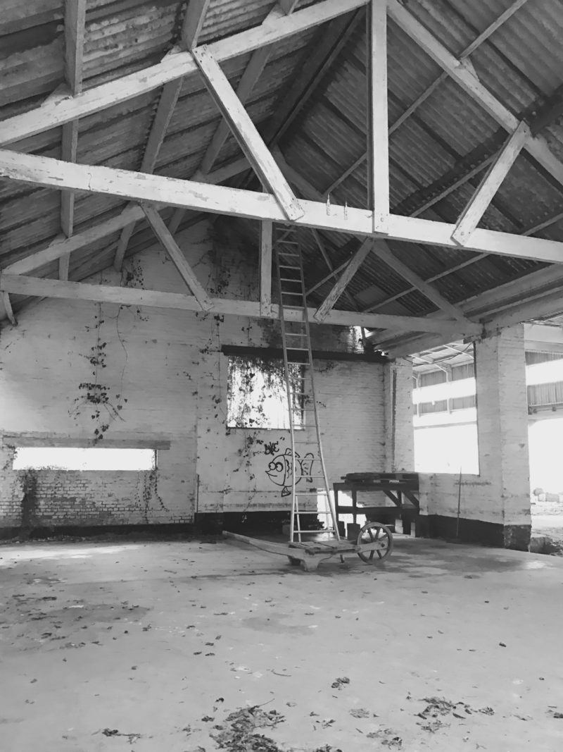
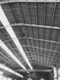
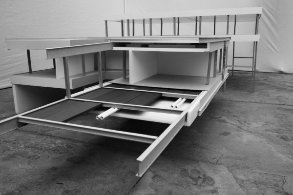
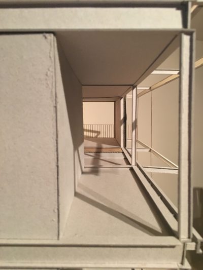
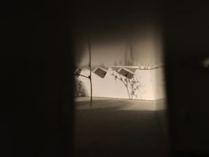
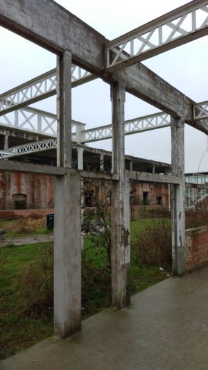
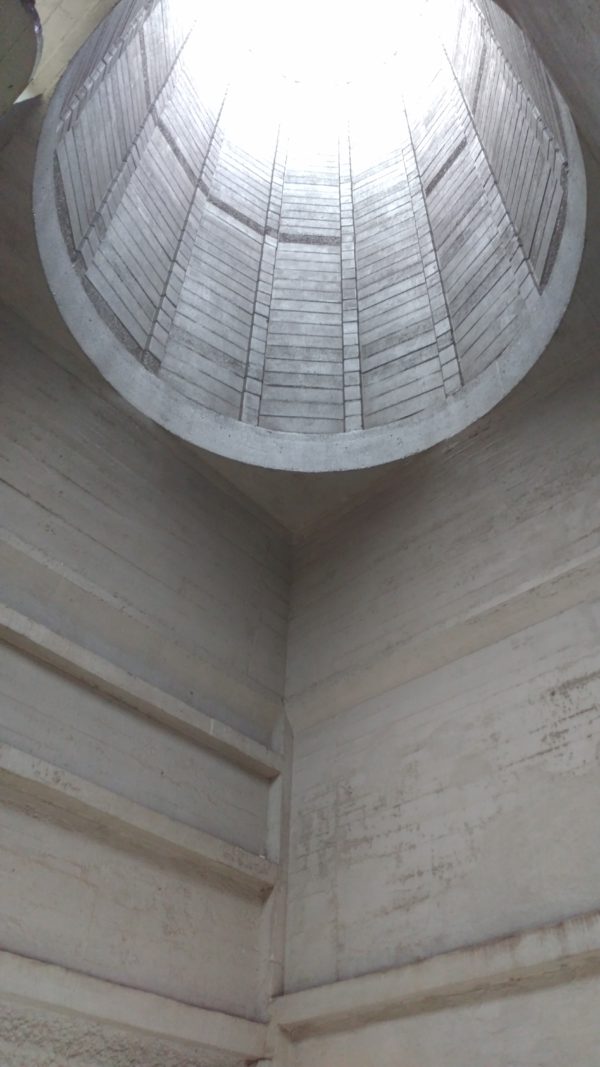
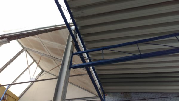
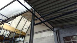
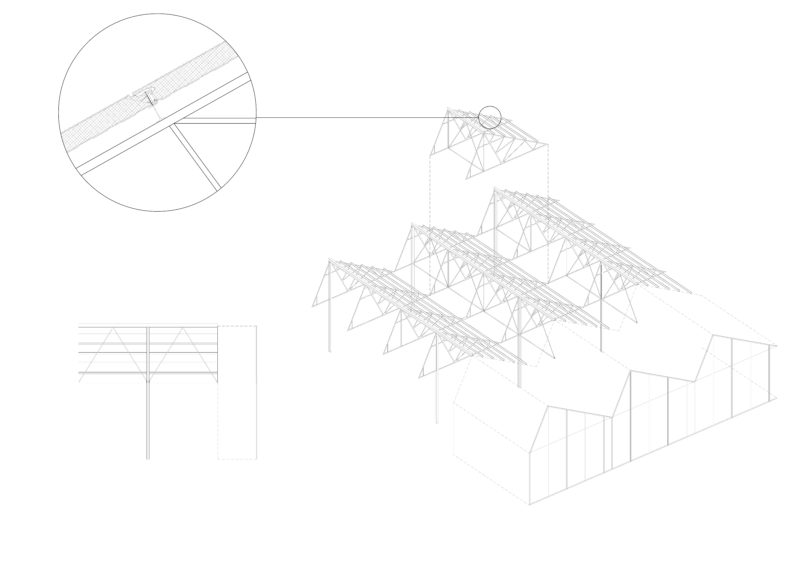
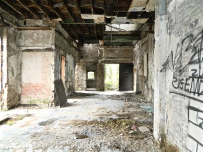
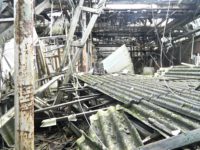
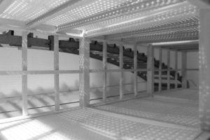
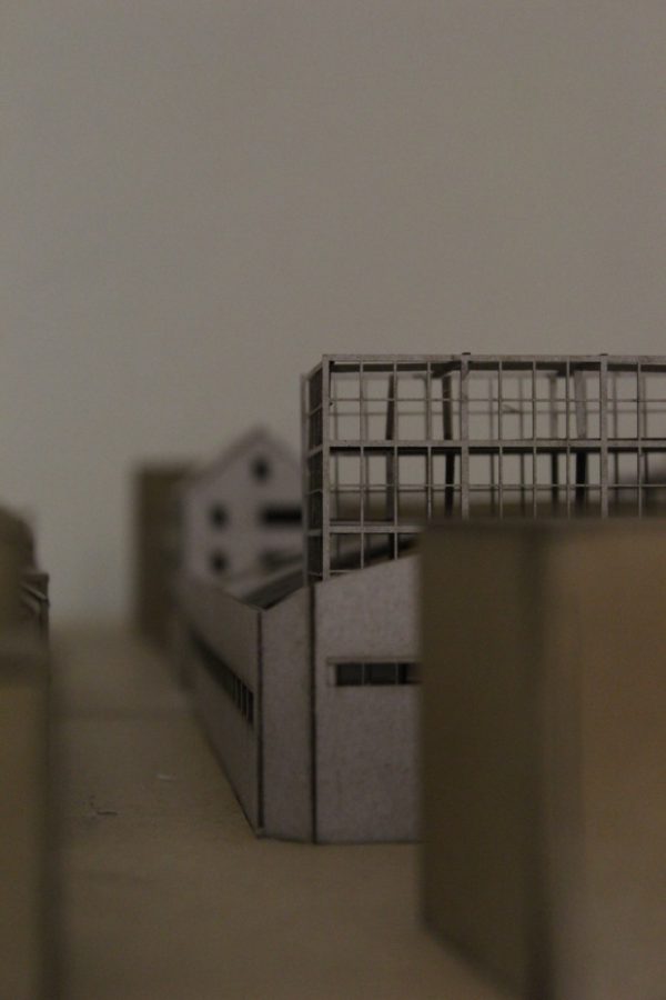
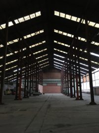
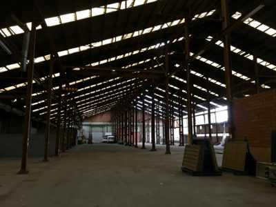
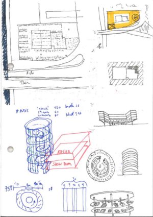
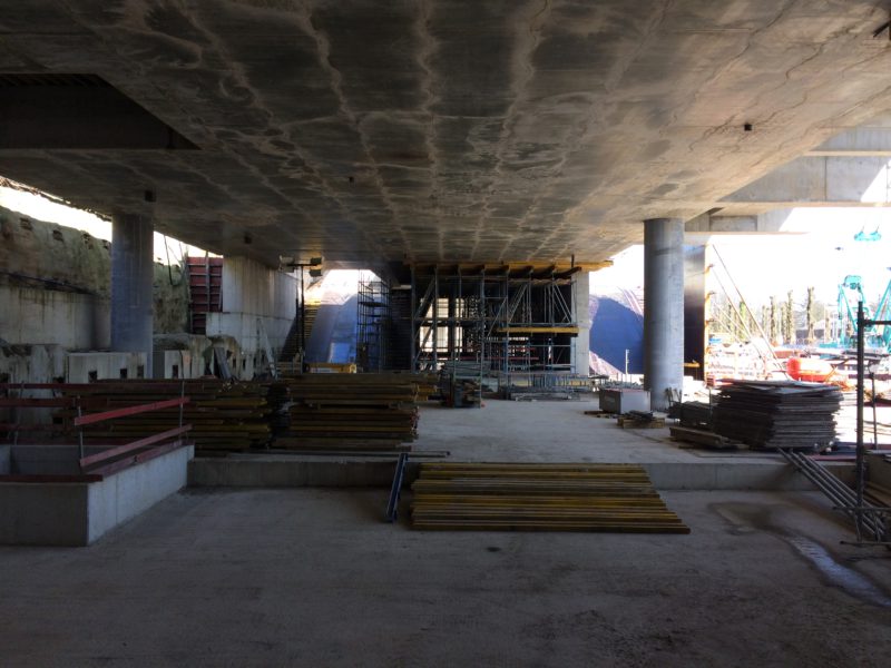
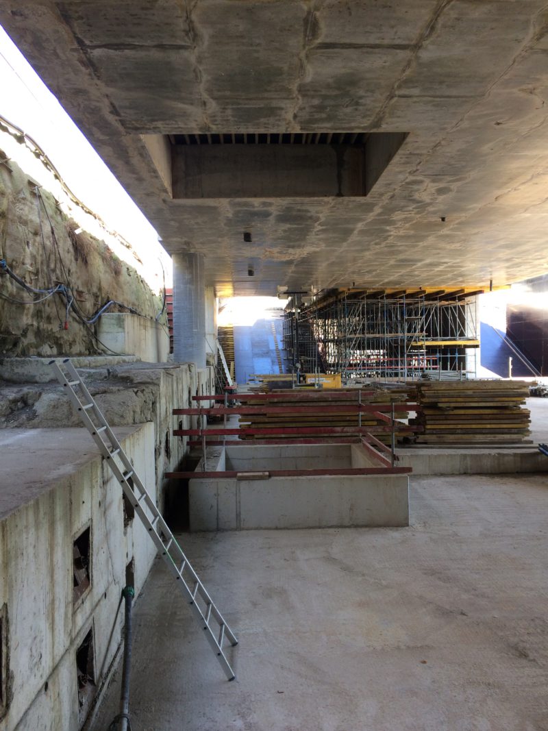
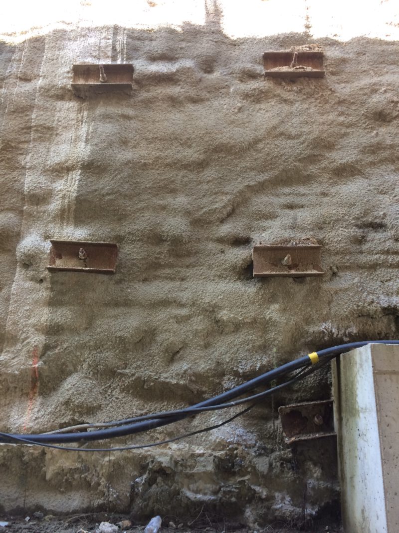
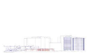
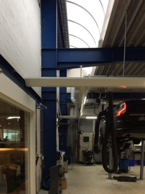
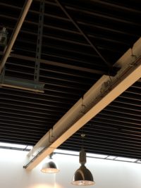
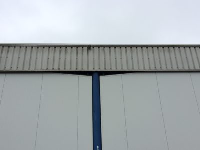
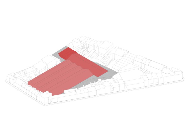
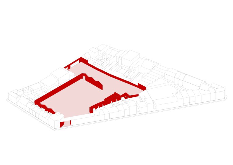
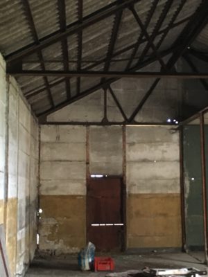
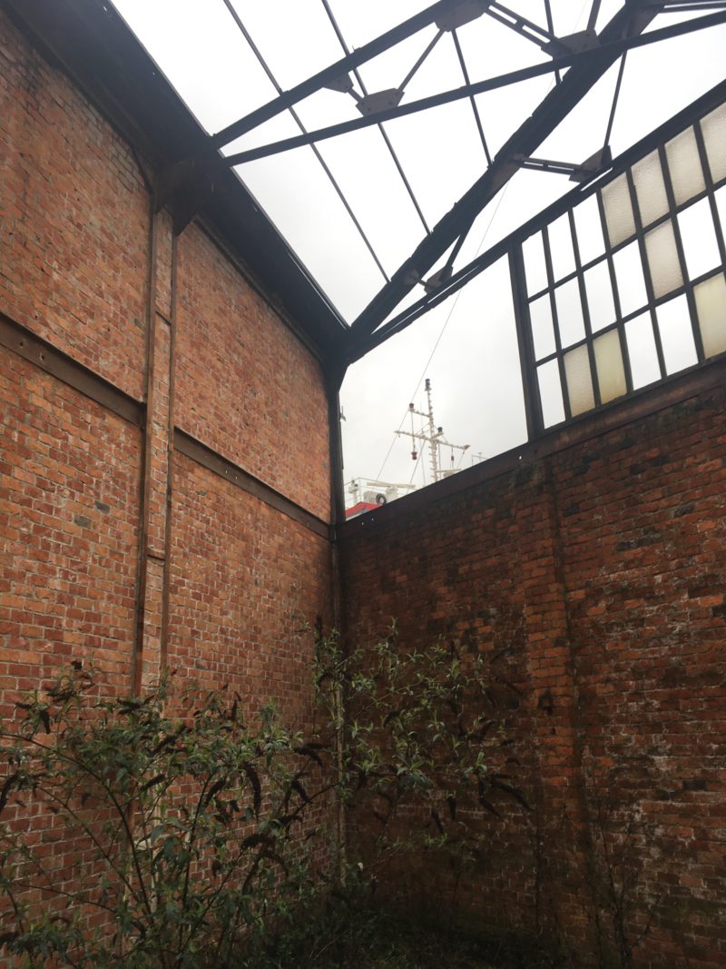
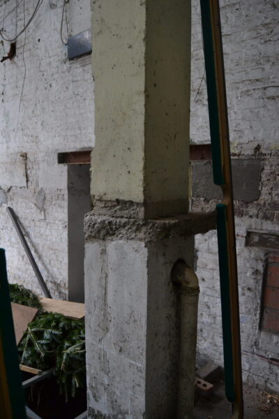
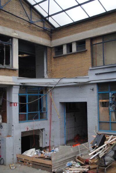
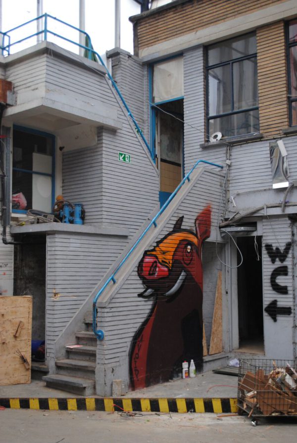
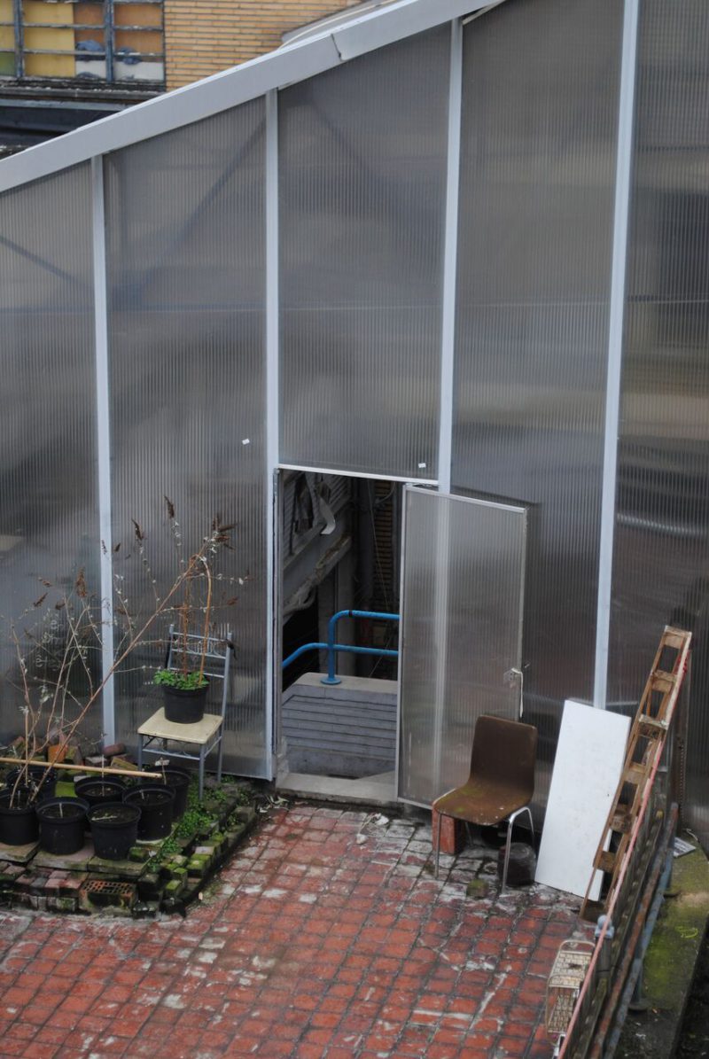
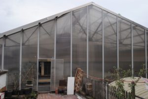
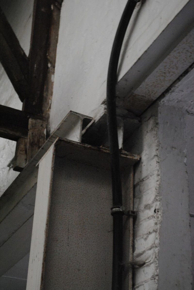
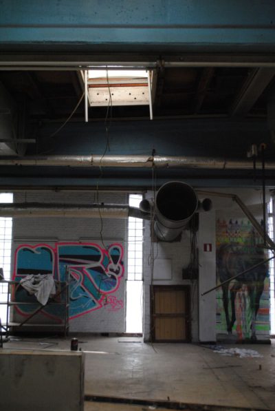
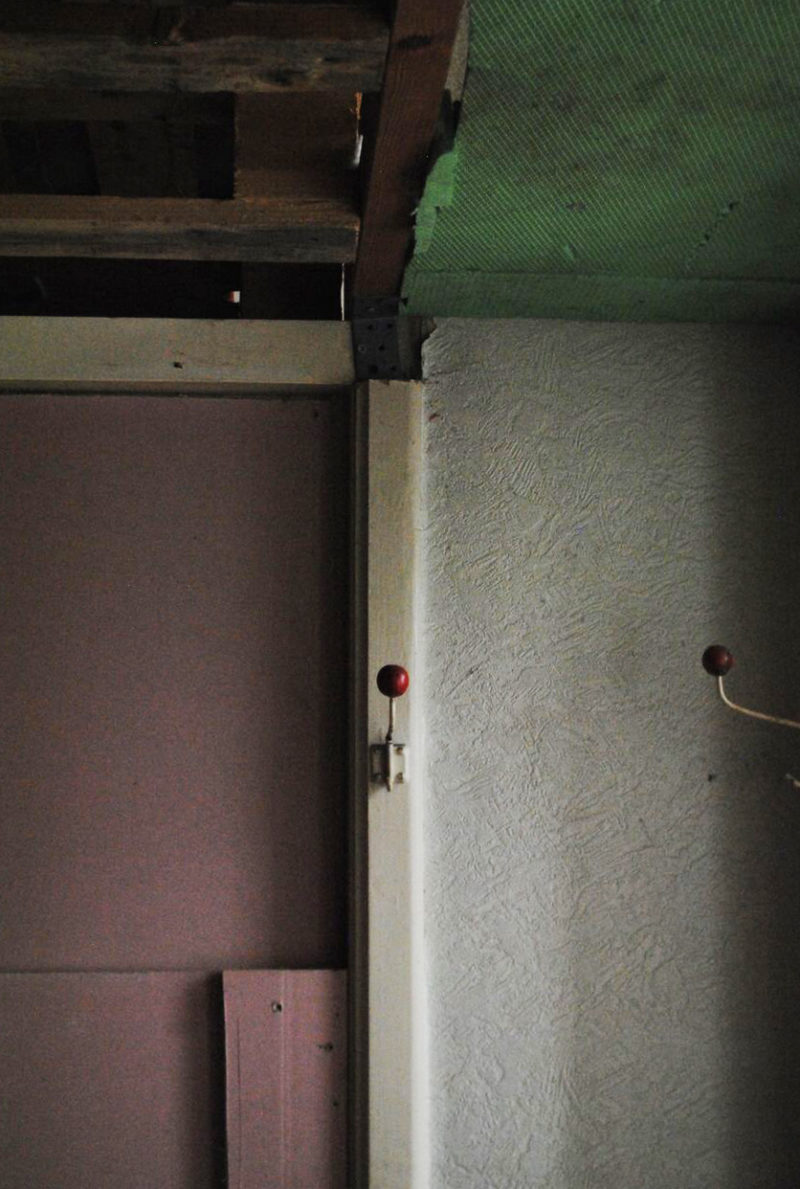
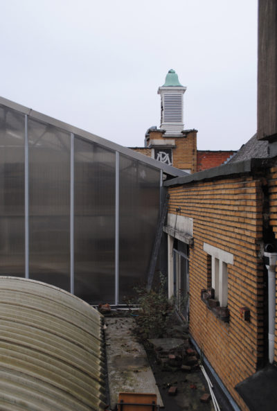
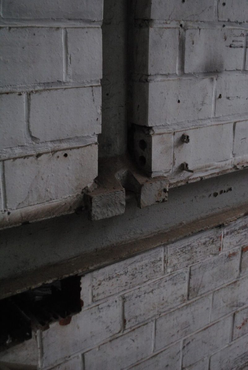
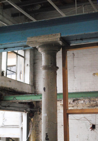
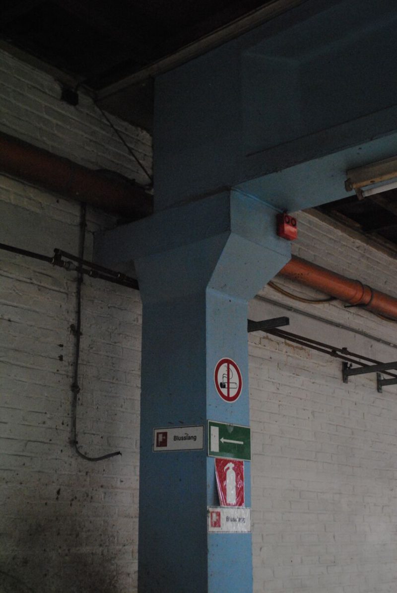
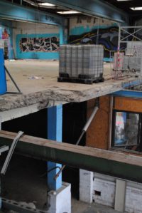
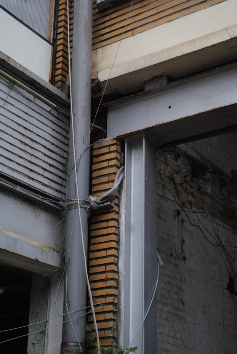
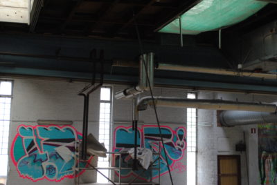
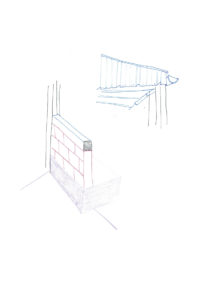
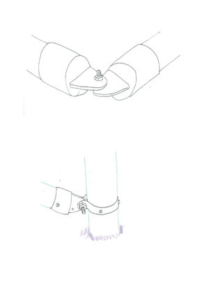
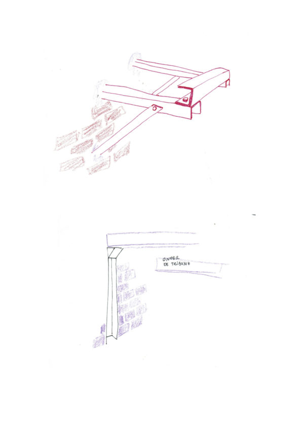
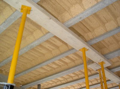
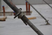
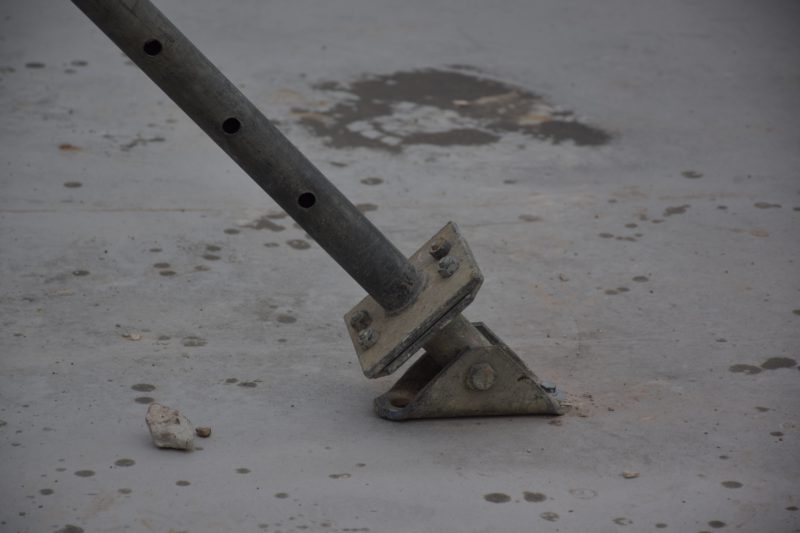
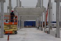
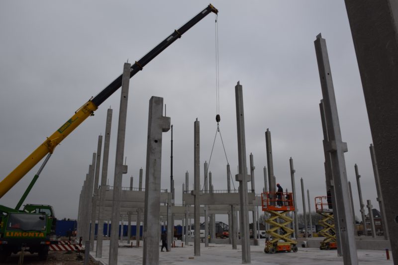
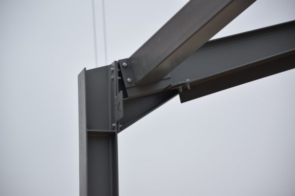
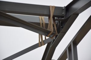
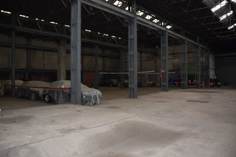
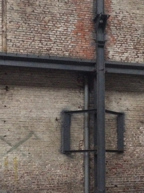
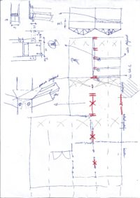
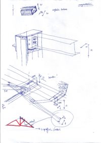
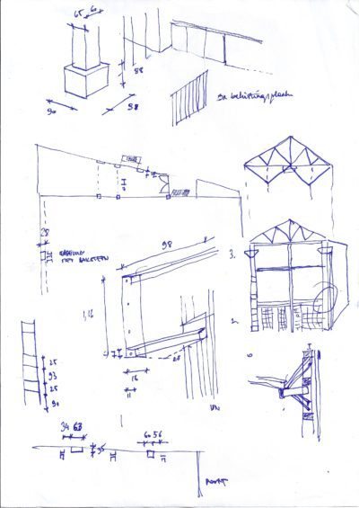
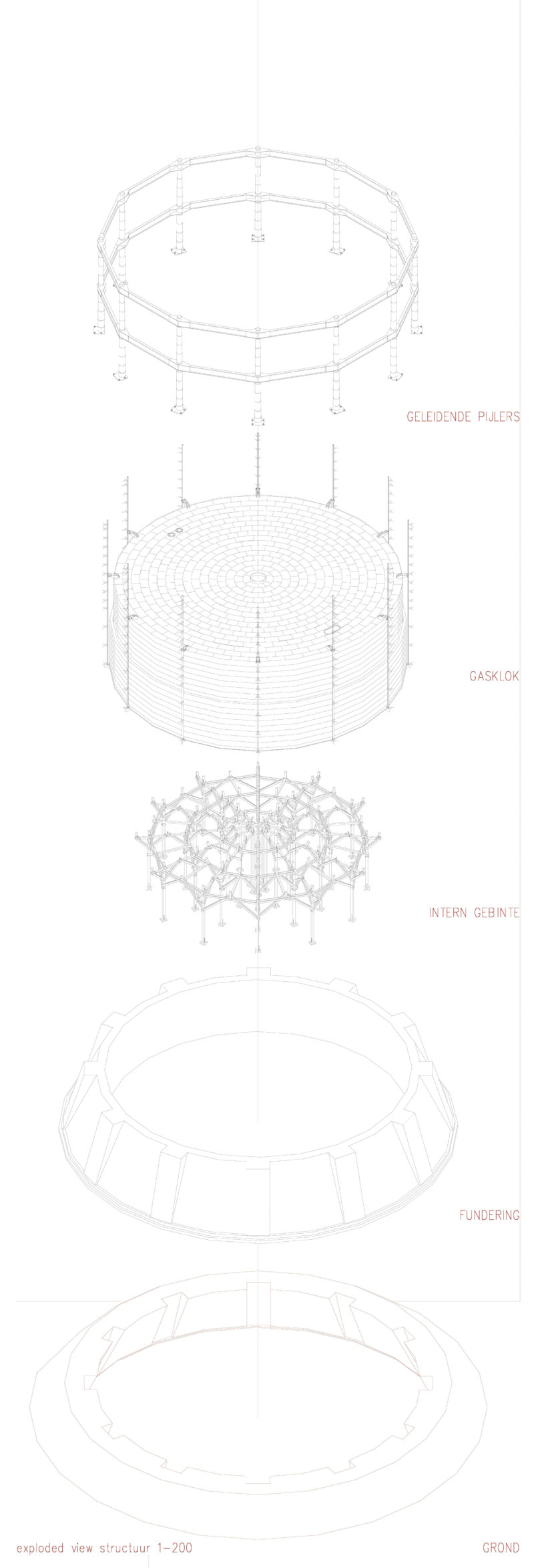
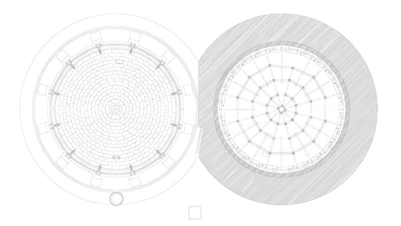
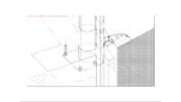
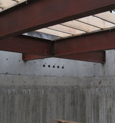
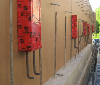
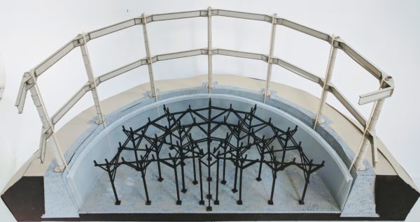
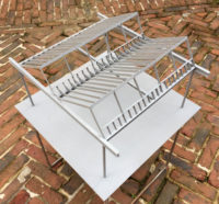
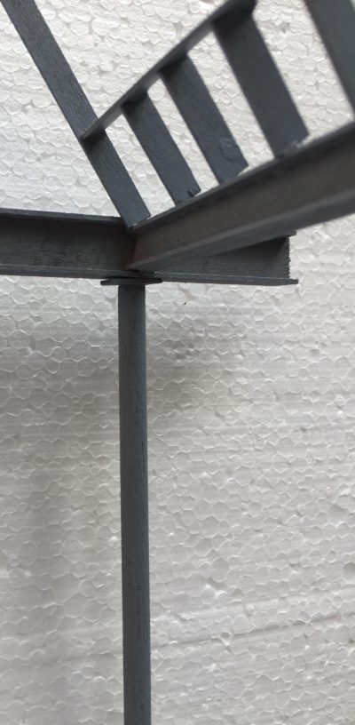
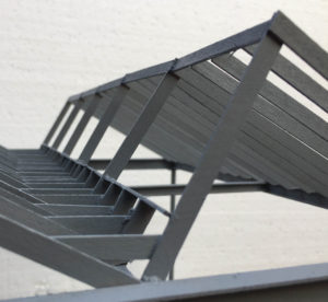
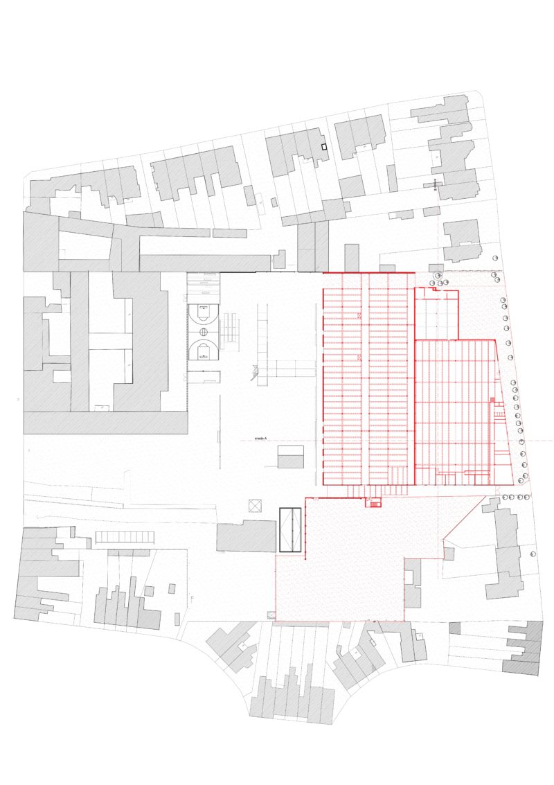
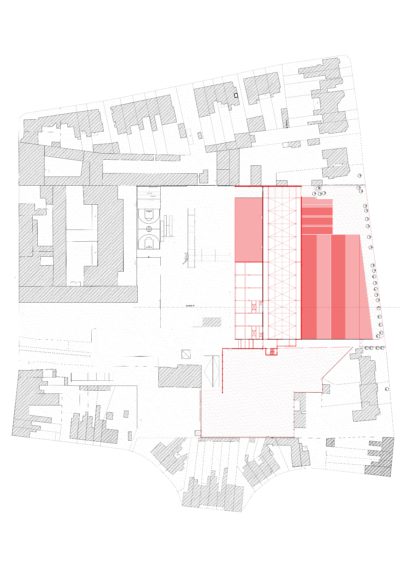
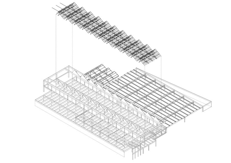
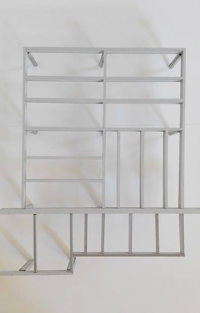
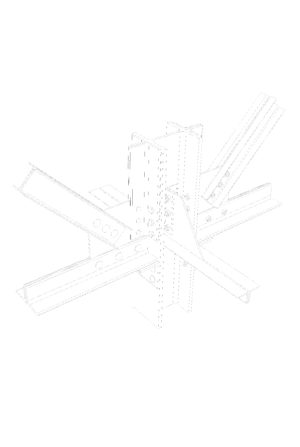
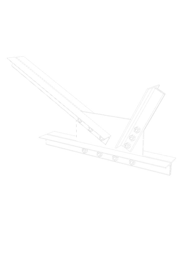
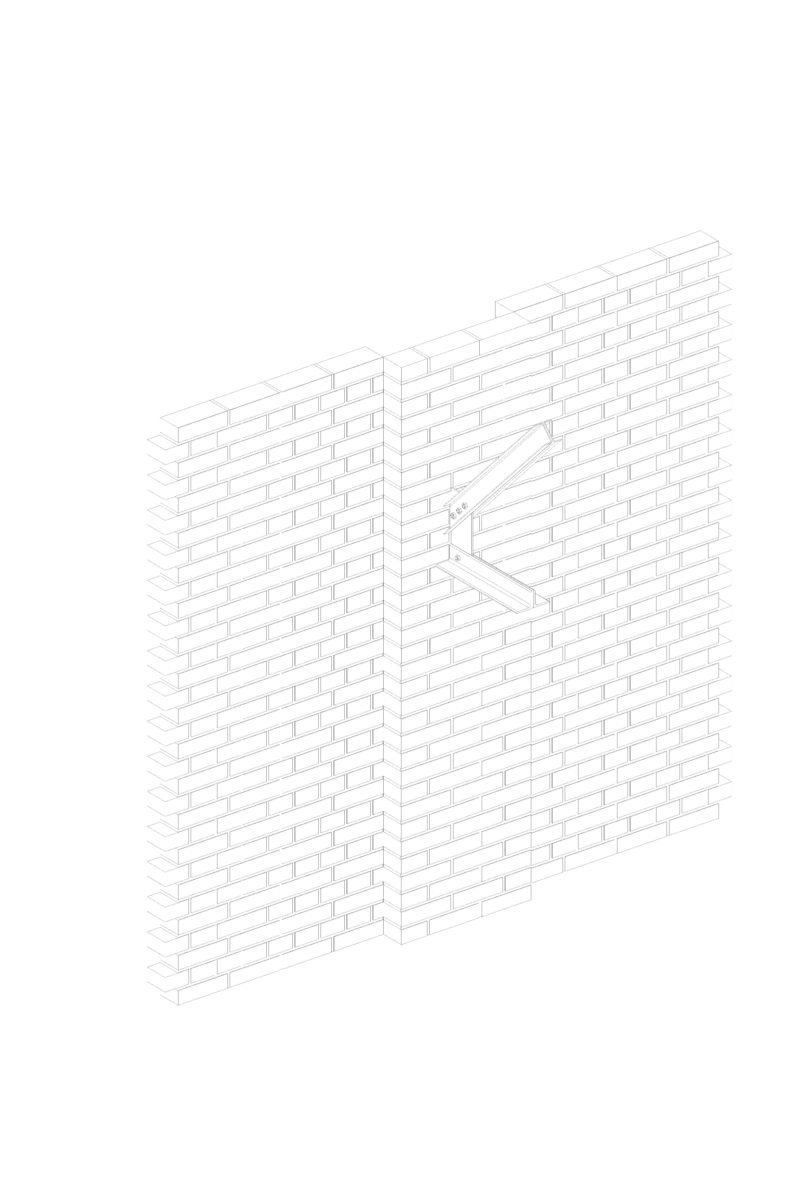
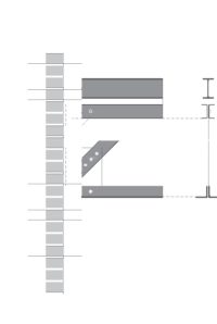
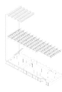
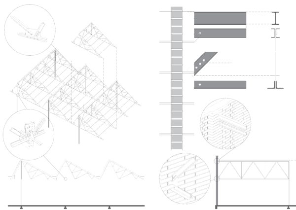
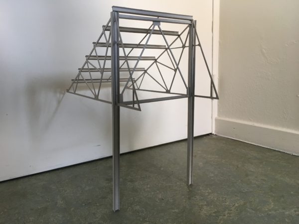
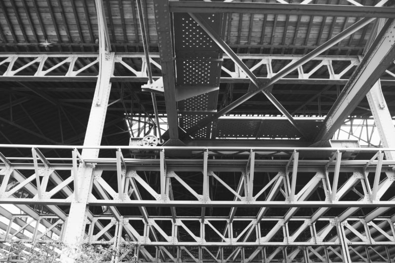
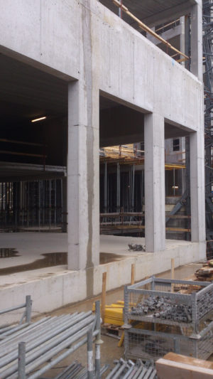
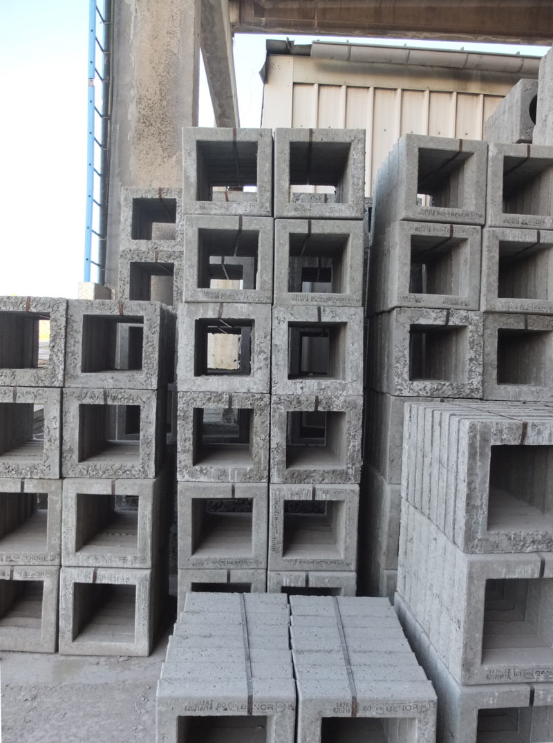
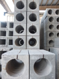
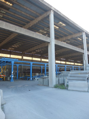
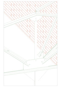
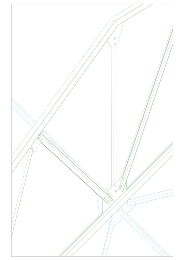
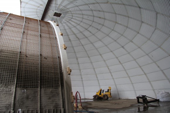
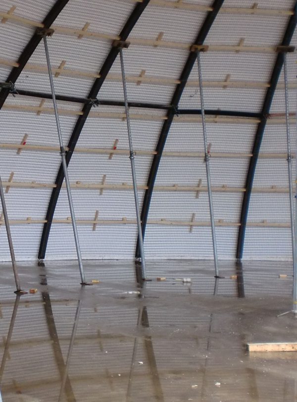
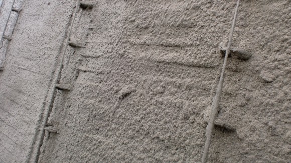
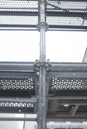
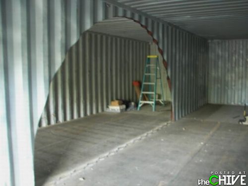
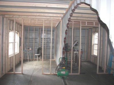
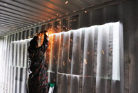
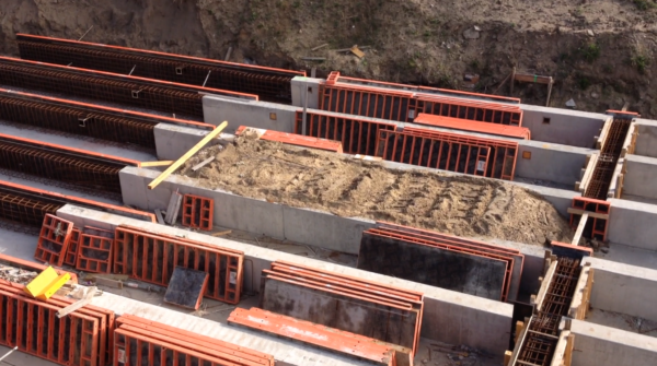
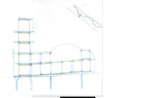
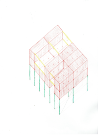
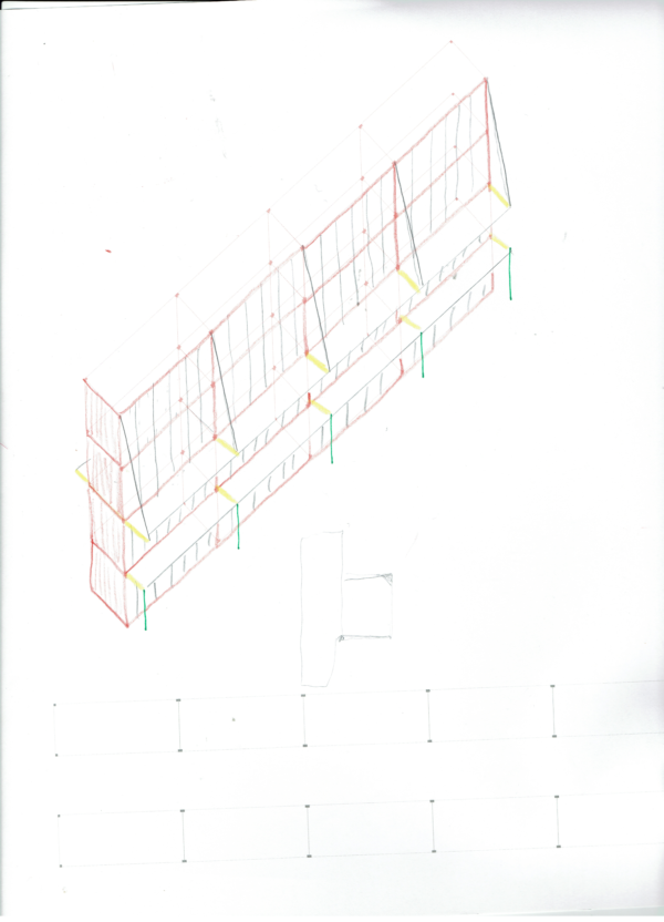
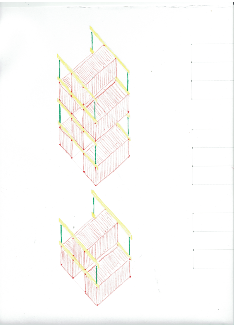
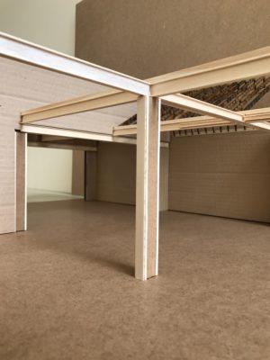
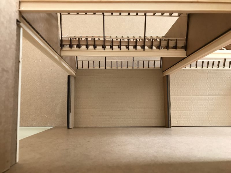
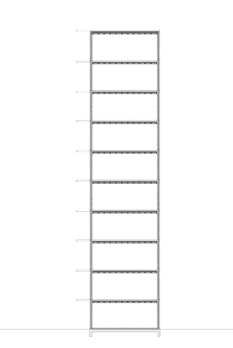
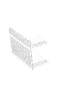
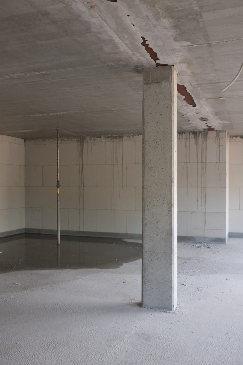
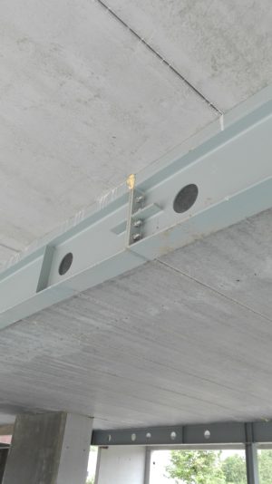
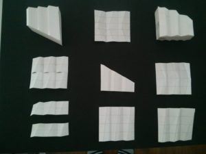
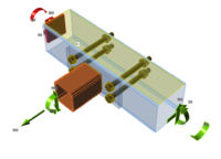
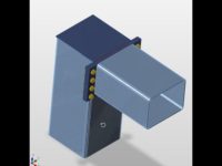
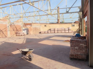
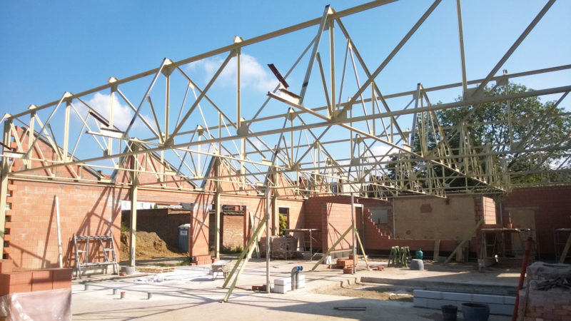
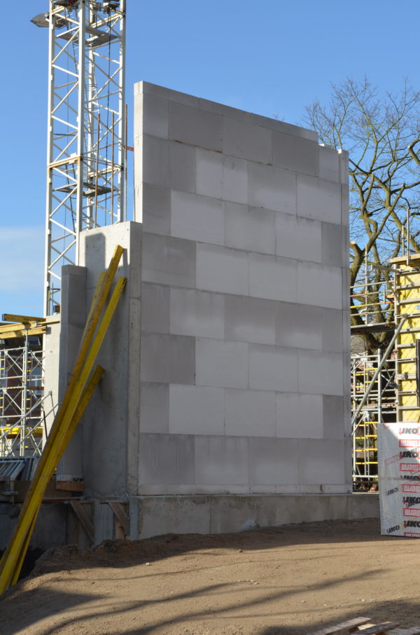
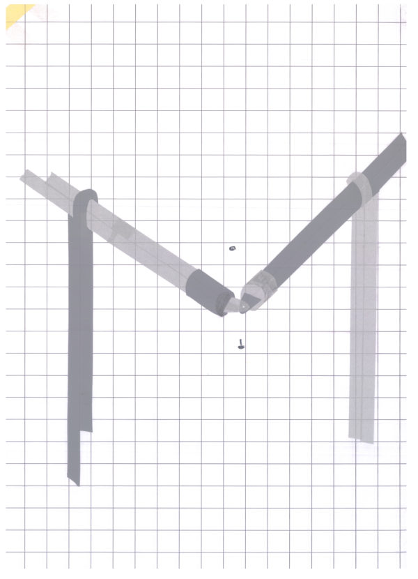
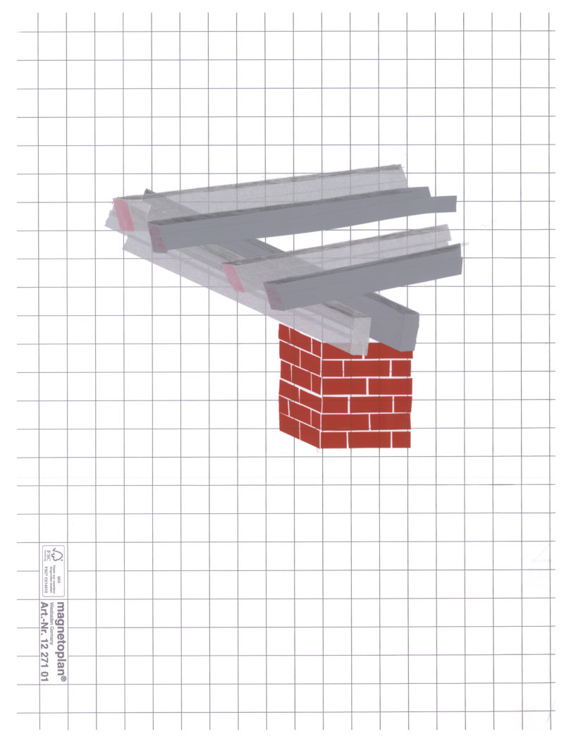
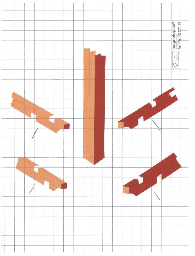
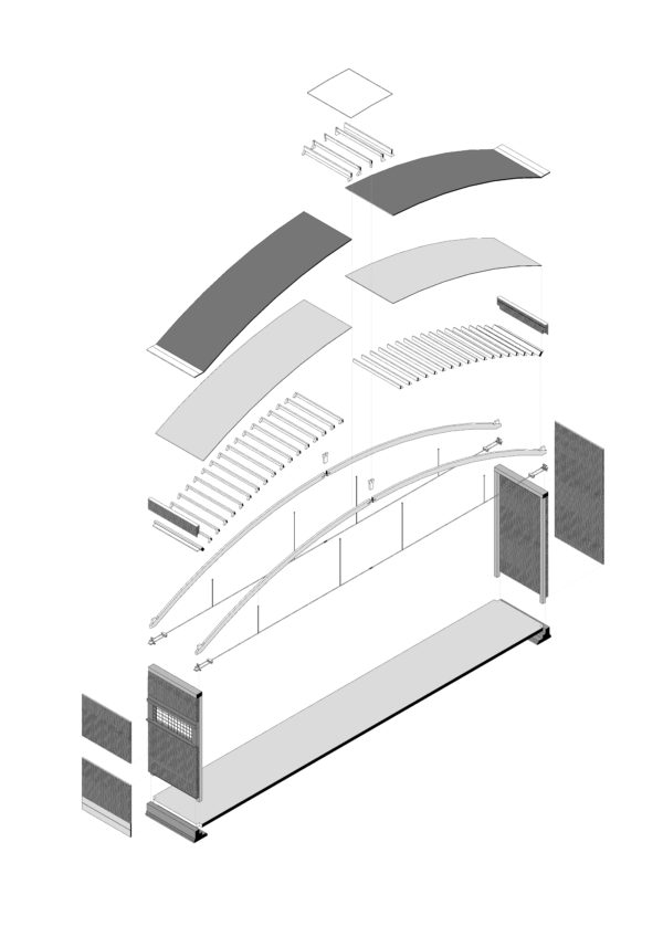
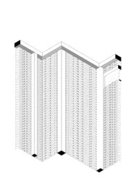
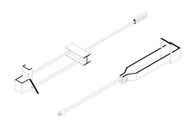
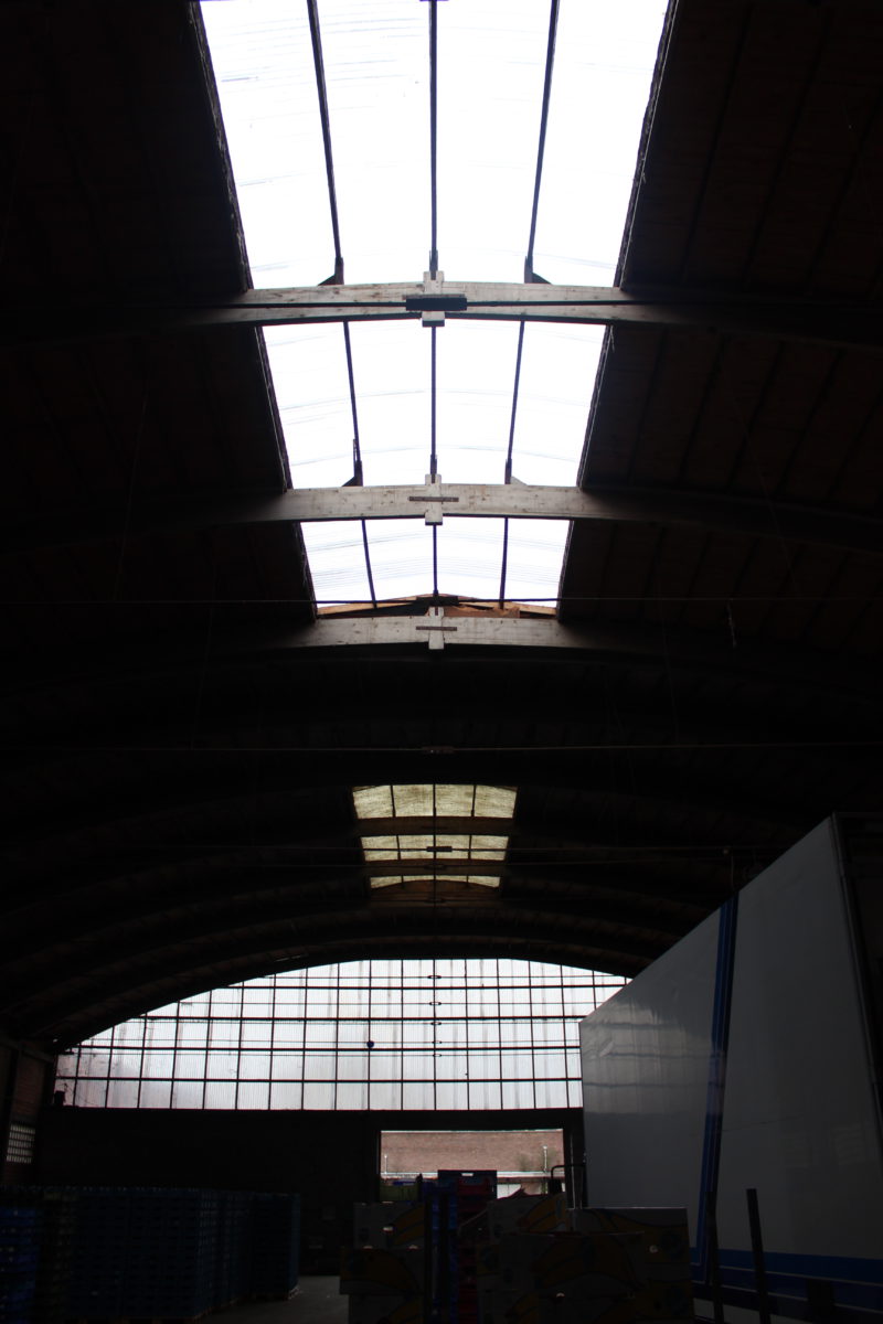
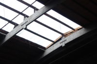
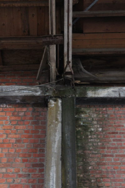
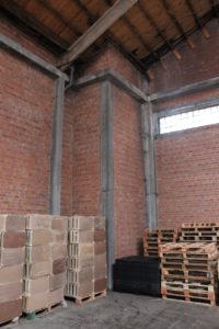
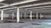
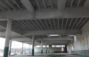
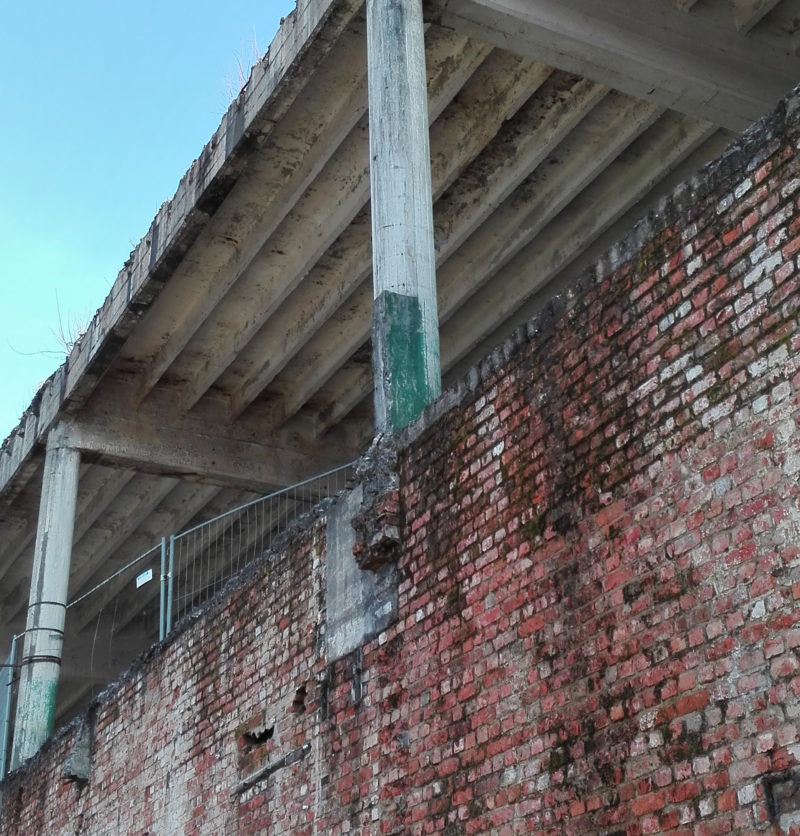
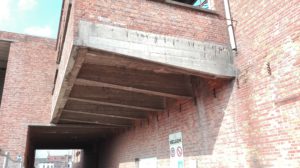
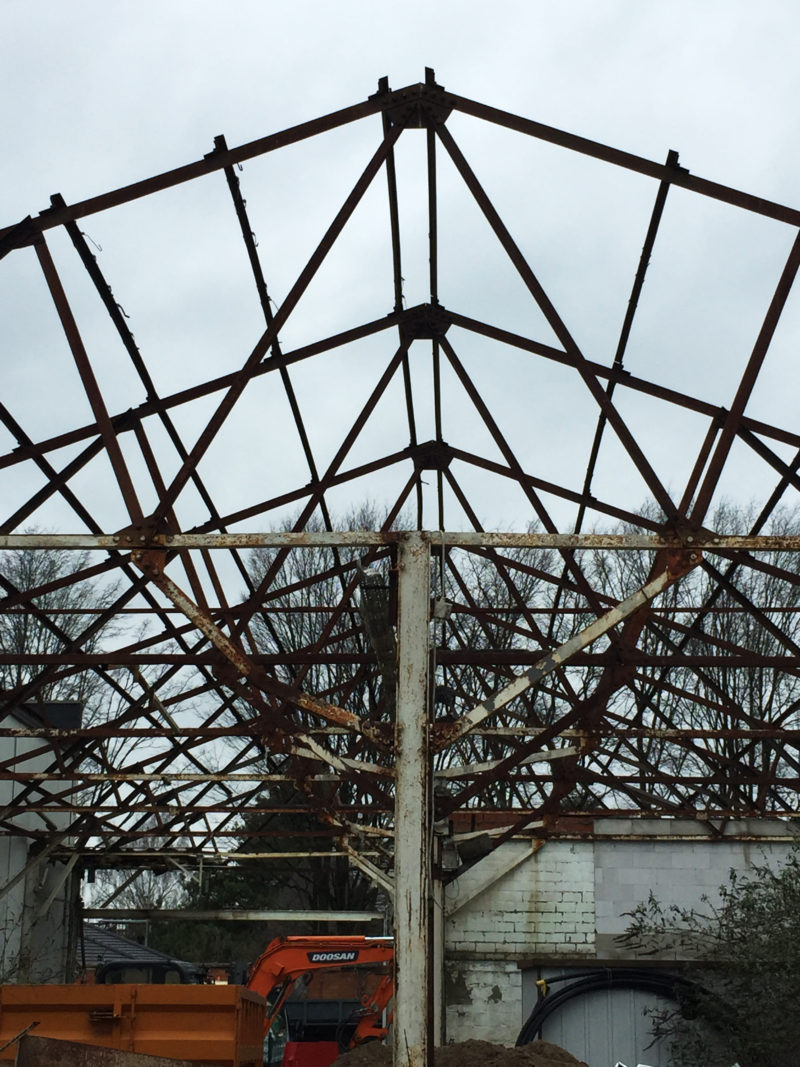
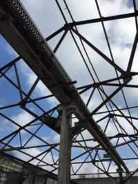
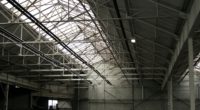
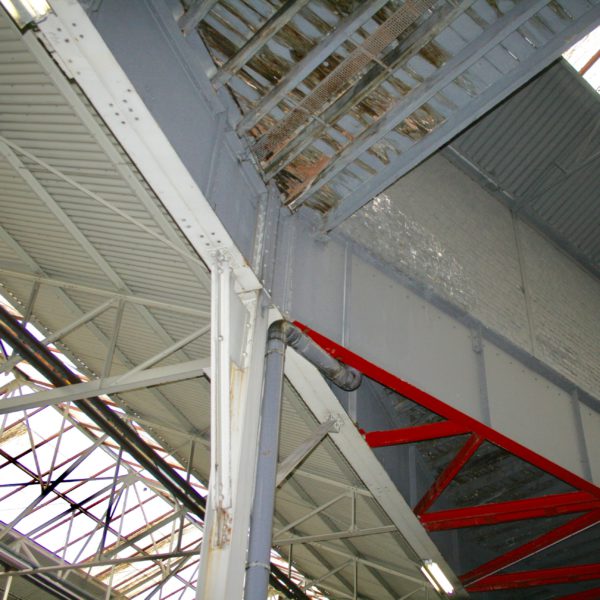
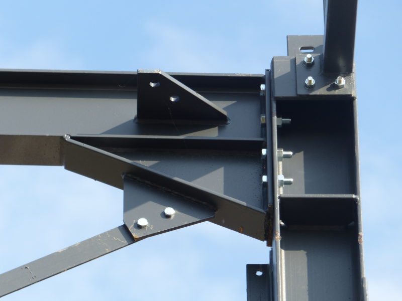
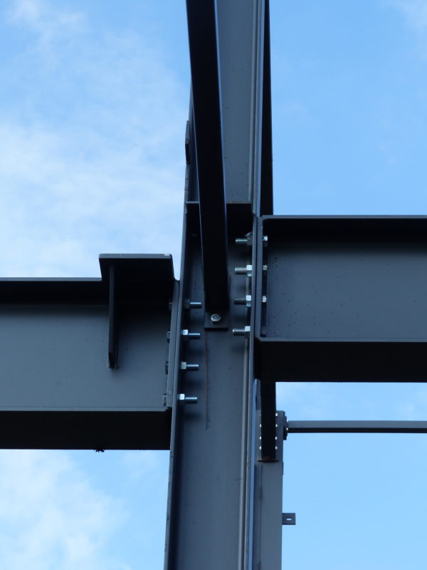
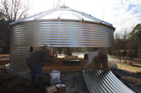
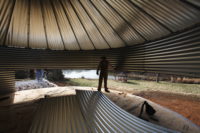
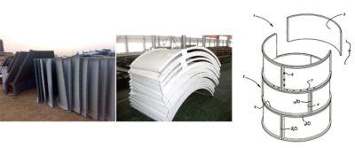
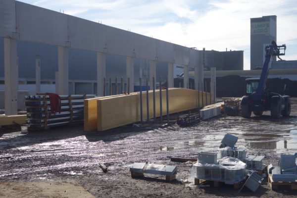
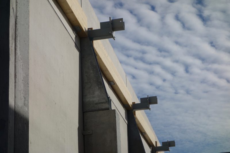
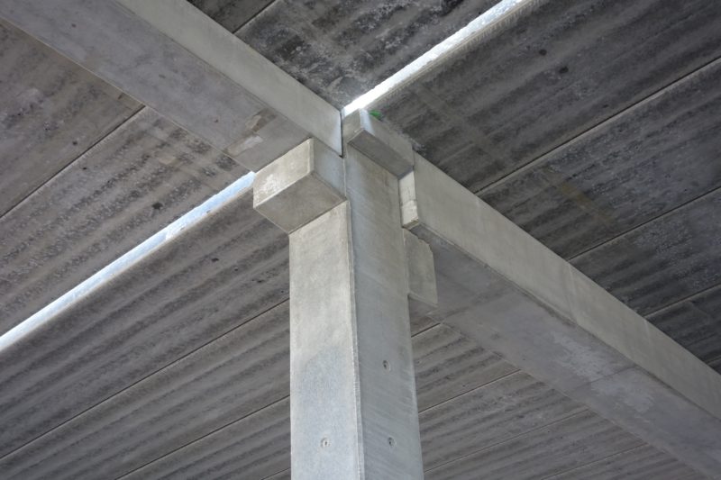
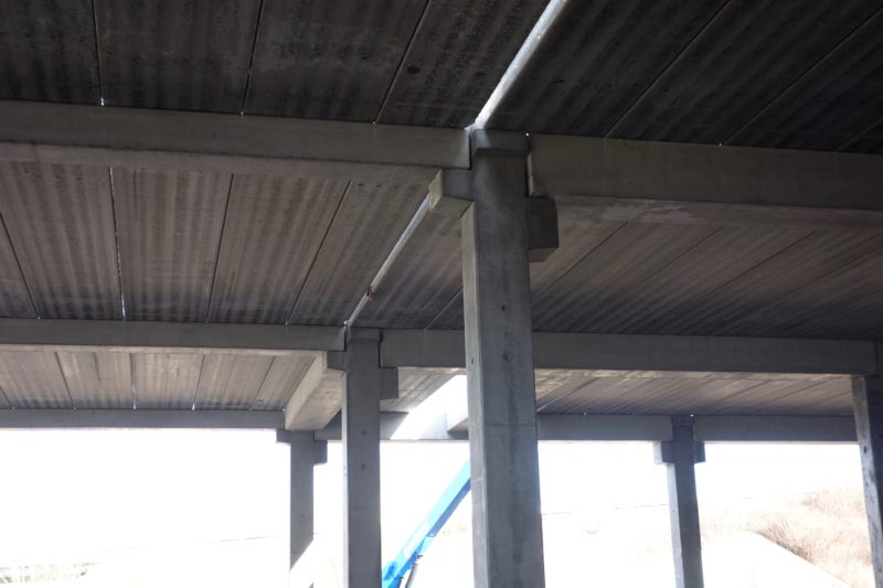
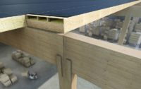
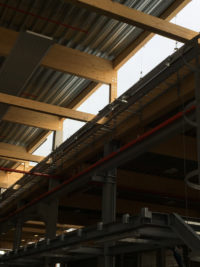
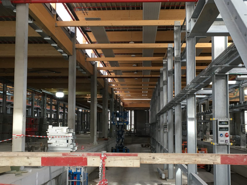
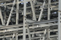
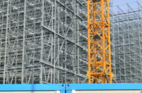
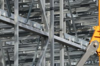
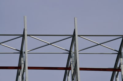
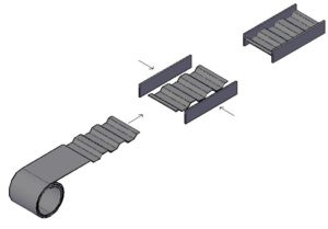
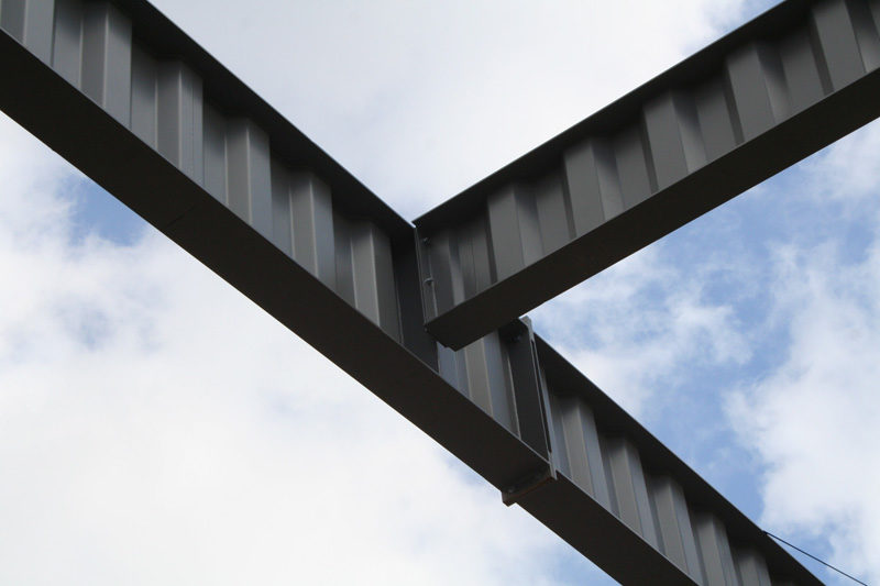
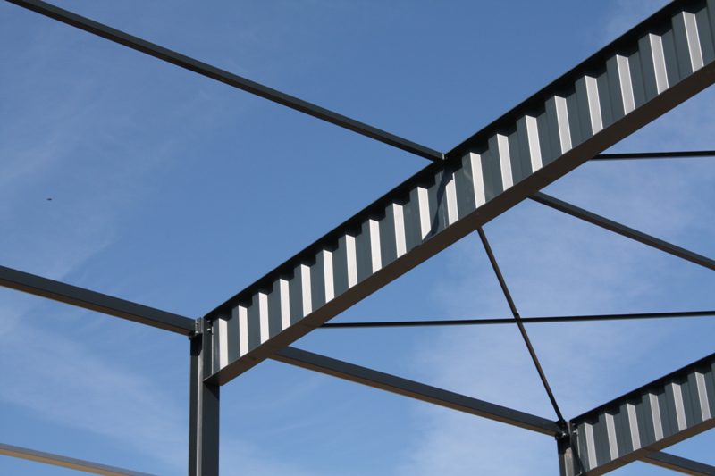
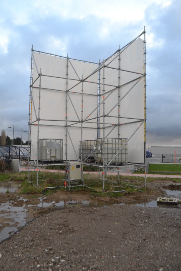
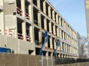
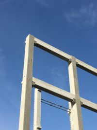
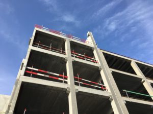
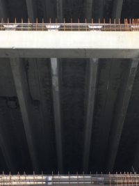
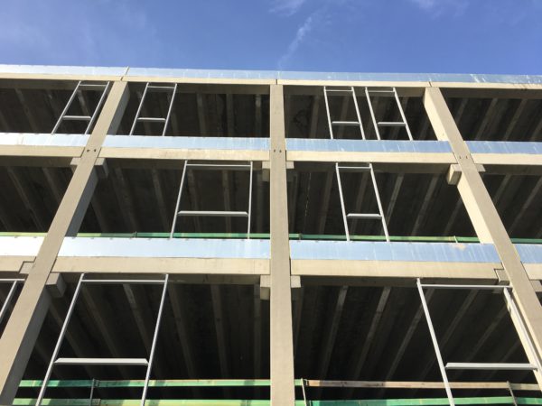
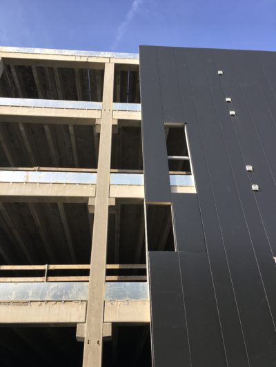
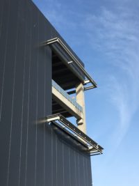
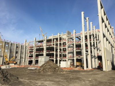
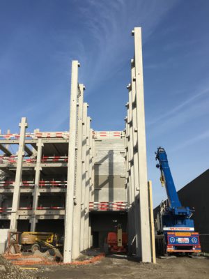
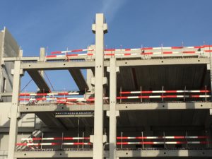
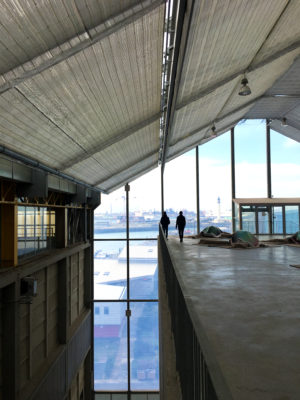
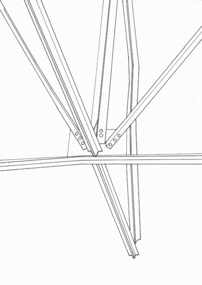
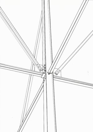
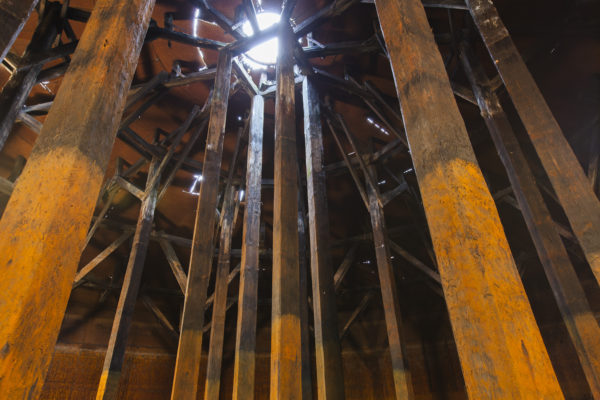
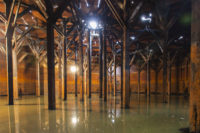
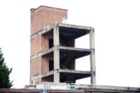
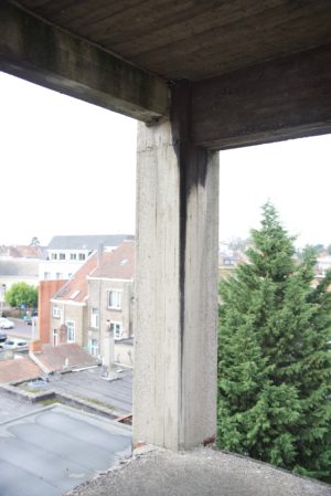
fig 4A, Hidden interior structure of the Tondelier sasholders, Interior of the Tondelier gasholders.
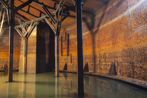
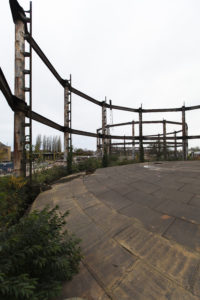
fig 4B, Hidden interior structure of the Tondelier sasholders, Interior of the Tondelier gasholders.
fig 4C, Hidden interior structure of the Tondelier sasholders, Interior of the Tondelier gasholders.
fig 4D, Hidden interior structure of the Tondelier sasholders, Remaining structure Tondelier gasholder
fig 3A, Voorhaven Site, The column is constructed with leftovers from the world expo in Antwerp 1985
fig 3B, Voorhaven Site
fig 3C, Voorhaven Site, how hot riveting is done.
fig 2A, ‘De Nobele’ – Site, Alongside the structure there's a workspace for a local artist.
fig 2B, ‘De Nobele’ – Site, The unfinished upper part of the old textile factory.
fig 2C, ‘De Nobele’ – Site, Detail of a main concrete column.
fig 2D, ‘De Nobele’ – Site, Analysis on which structure stays and which one disappears.
fig 2E, ‘De Nobele’ – Site, Detail of the naked concrete structure.
fig 1A, STEEL JOINT